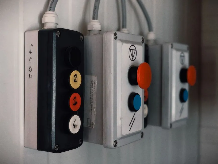
A compliant anti-static grounding system for electronics manufacturing is built from four hardware tiers, wrist straps, workbench mats, common-point ground bars, and static-dissipative floor finishes, tied together to keep human body voltage under 100 V and limit the resistance from any conductive surface to the equipment-grounding conductor at 1×10⁶ to 1×10⁹ Ω, per ANSI/ESD S20.20-2021 and IEC TR 61340-1:2015 [S2][S3].
The system only works as a single equipotential network: a dissipative mat is meaningless if the operator floats at 1,500 V. Verification uses a contact-discharge test (residual under 100 V) for personnel and a surface-resistance meter (1×10⁶ to 1×10⁹ Ω) for the bench top, repeated on a documented cadence [S3]. A process-engineer-grade program also confirms the common point ground (CPG) resistance to the facility equipment ground is below 1 Ω, which is the same bonding target used in safety grounding under NFPA 70 Article 250.
System Architecture: Four Hardware Tiers and One Equipotential Bond
The standard EPA (electrostatic protected area) grounding chain has a fixed hierarchy, and a missing link anywhere in it breaks the program. From the operator outward it runs: wrist strap with coiled cord, ESD workbench mat (typically 2 mm thick, two-layer rubber with a conductive buried scrim), common point ground bar, and static-dissipative floor or floor mat, with each tier resistance-bounded to the next [S2][S4].
Keyence's electrical-and-electronics product line and Static Solutions' bench products both implement this chain, supplying wrist straps, mat kits, foot grounders, constant monitors, and field meters as bundled rather than piecemeal items [S1][S6]. The Rhino Cutting Mat ESD range illustrates the typical product mix on the workbench side: an ESD bench mat, a popper-style wrist strap, and an ESD work-surface mat sold as matched items rather than independent SKUs [S4].
The common point ground is the single node that ties wrist straps, bench mats, and tool grounds to the facility equipment ground, and it must read below 1 Ω to that ground, otherwise the chain cannot bleed charge fast enough during a charged-device event [S3]. Incompliancemag's June 2026 grounding primer restates the same target: a safe, low-impedance path to earth, not to a stray water pipe or structural steel that may float [S7].
Resistance Targets, Voltage Limits, and Measurement Methods
Every tier has a published resistance window, and process engineers should write those numbers into the audit checklist rather than relying on a generic "is it grounded?" question. For personnel grounding the verification target is under 100 V residual body voltage after a simulated contact discharge; for tools and work surfaces the resistance-to-ground target is typically 1×10⁶ to 1×10⁹ Ω; and the CPG to facility ground is under 1 Ω [S2][S3].
Discharge-time limits are an equally important but often ignored number: a dissipative mat should bleed a 1,000 V charge to under 100 V in less than 2 seconds, which is the dissipative band, not the conductive band (sub-1 s) and not the insulative band (over 10 s) [S3]. ANSI/ESD STM4.1 governs that measurement on worksurface mats, and ANSI/ESD S1.1 governs wrist-strap testing; both belong in the qualification file for any new mat or strap SKU.
Humidity control is the other hidden variable. Data referenced from the EOS/ESD Symposium 2023 proceedings shows ESD event frequency rising 18.7% (±2.3%) once indoor relative humidity drops below 30% [S3]. A grounding program that ignores humidification is reading the wrong page of the standard.
Selection Criteria: Bench Mat vs Floor Mat vs Ionizer vs Wrist Strap
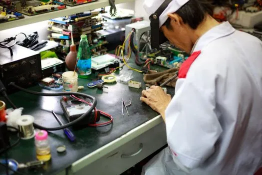
Choosing hardware by resistance class alone is a common procurement mistake. The four main options solve different problems and should be specified against a fixed criterion set: where the charge originates, the required discharge time, the operator's mobility, and the verification burden. The table below lines the four options up against those four criteria for a typical SMT or PCB assembly cell. [S2]
Wrist straps win on mobility cost (under $20 per station) and direct personnel discharge path, but they fail mobility because they tether the operator, which is why foot grounders plus a floor mat are specified for cells where staff walk between stations [S1][S2]. ESD bench mats dominate seated PCB assembly because the 1×10⁶ to 1×10⁹ Ω band dissipates charge in the 1-2 s window without the spark risk of a conductive surface, and they also protect the bench mechanically. Ionizers, either overhead bars or benchtop units, are the only tier that can neutralize insulators that cannot be grounded, such as plastic component trays, paper work instructions, or mylar sheets, and they are required wherever those insulators enter the EPA [S2][S5].
Anti-static mats in defence electronics manufacturing carry an extra documentation burden, with procurement often asking for lot-level resistivity data and an IEC 61340-1 traceability certificate, and the Rhino product page for the SupaSeal Anti-Static mat family reflects that demand for auditable ESD SKU records [S4]. A 2026 buyer comparing mat vendors should treat per-SKU resistivity certificates and the option of a field constant monitor as differentiators, not as bonus features.
Standards Stack: ANSI/ESD S20.20, IEC 61340-1, and the 61340-5-x Test Methods
ANSI/ESD S20.20-2021 is the program-level standard for any US-domiciled EPA, and IEC 61340-1:2015 is the parallel European technical report covering terminology and general principles, while IEC 61340-5-1 covers the European protection-implementation requirements and 61340-5-2 covers the user-guide section [S2][S3]. The ANSI/ESD/JEDEC joint standards JS-001 (HBM) and JS-002 (CDM) define component-level withstand ratings that feed back into the program; a 30 V discharge can damage some modern ICs, so even Class 0A devices need a controlled EPA even if the line is not handling bare dice [S2].
For labelling, the reaching-hand-in-triangle (ESD Susceptibility) and the bold-circle-with-three-arrows (ESD Protective) symbols are derived from ANSI/ESD S8.1-2007, and showing both on a bag or workstation is the visual proof that the program is wired to a published standard rather than to folklore [S5]. The same standards family is what auditors under AS9100D or IATF 16949 will check during a surveillance visit, so writing the standard number into the work instruction is the cheapest defense.
Who an EPA Grounding Program Is For, and Where It Is Overkill

An EPA grounding program is non-negotiable for any line that handles bare printed circuit boards, populated boards before conformal coat, semiconductor devices below Class 1C HBM (under 1,000 V), and any production step using wave or selective soldering where the board leaves the grounded fixture. It is also mandatory in defence electronics manufacturing, medical device assembly, and any site shipping to automotive Tier-1 customers running IATF 16949 audits, where the mat-and-wrist-strap chain is a routine audit finding [S2][S4].
It is overkill for fully encapsulated, potted, or chassis-mounted assemblies where no ESD-sensitive component is exposed during the process step, for finished-product packaging areas where the unit ships in a sealed ESD bag, and for any outdoor or uncontrolled-humidity environment where a 1×10⁹ Ω mat can leak charge faster than the static accumulates. In those cases, ionizers or simply relocating the EPA boundary to the next station is the cheaper answer than re-engineering the floor.
Verification Cadence and the Real Source of Field Failures
The most common field failure is not a broken mat, it is an open wrist-strap coil cord that still passes a continuity beep but fails under flex. The fix is a constant monitor that watches the loop resistance and the operator's body voltage in real time, with an alarm threshold around 35 MΩ (the typical upper limit for a wrist-strap loop) and a body-voltage alarm around 100 V [S2][S3]. Pre-shift wrist-strap testing using a pass/fail tester is the legal minimum; constant monitoring is the engineering best practice and what most Tier-1 automotive audits now require.
Those numbers are the kind of evidence worth bringing into an internal capital request when justifying a constant-monitor rollout.
Common Failure Modes and How to Spec Against Them
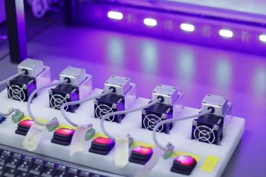
Three failure modes dominate field reports. First, mat-to-ground snap studs that lose tension after 6-12 months, raising the CPG resistance above the 1 Ω target, fixable by specifying 10 mm machined brass studs rather than pressed steel. Second, ESD floor finishes that were never re-applied per the supplier's 12-month re-coat schedule, which pushes the surface back into the insulative band, fixable by writing the re-coat date into the floor-care contract. Third, ionizers that drift out of balance, which turns them from a neutralizer into a charger, fixable by specifying a ±50 V auto-balance ionizer with a 6-month calibration certificate rather than a fixed-output bar [S2][S5].
A spec-first buyer writing an RFQ for an anti-static equipment bundle should require: per-SKU resistivity traceable to IEC 61340-5-1, a CPG resistance test report under 1 Ω, an ionizer balance certificate under ±50 V, and a constant-monitor specification with audible alarm below 35 MΩ loop resistance. Vague language like "ESD-safe" or "static-dissipative" without a resistance band is a red flag, since "static-dissipative" only has a defined meaning if the number 1×10⁶ to 1×10⁹ Ω sits next to it [S3][S4].
For a construction-machinery buyer, the most relevant cross-over is the CPG bonding target under 1 Ω, which is the same limit used in safety grounding for heavy equipment per NFPA 70 Article 250, and the same constant-monitoring logic used on NDT carts to verify a ground loop before energizing a probe.
Trackable signals to watch over the next two quarters: any revision notice for ANSI/ESD S20.20 (the 2021 edition is the active version), IEC 61340-5-1 amendments, and the EU's ongoing harmonization of the 61340-5-x series under the Low Voltage Directive. Pairing a known additive-manufacturing material chain with an ESD-traceable program is also worth a follow-up if your site moves to 3D-printed fixturing, since most engineering-grade polymers are insulative and need a topical anti-static coating to stay inside the EPA.
For related coverage, see Bipolar Plate Stamping and Laser Welding Automation for PEM Fuel Cells.