
An AWWA C502 dry-barrel hydrant is defined by where its main valve sits (below the frost line) and how that valve opens against the line pressure, not by outlet threading or breakaway-flange design. Two main valve geometries are described in the standard's family of documents: compression type and slide-gate type, plus a third toggle variant for legacy stock [S2].
Compression and slide-gate are mechanically distinct. Compression units move the main valve reciprocally on a vertical axis against a fixed seat; the stem travels straight up and down when the operating nut is rotated. Slide-gate units move a gate vertically on a threaded stem, with a wedging mechanism forcing the gate into the seat at the base of the hydrant [S2]. Both are dry-barrel configurations governed by AWWA C502 with the typical 5¼ in main valve opening and 250 psi working pressure class [S1][S7][S8].
Main valve geometry: stem path, seat location, opening force
In a compression hydrant the main valve can be configured either below the seat, opening against line pressure, or above the seat, opening with line pressure; the stem moves linearly and the seal is achieved by seating against a fixed bronze or rubber-faced ring [S2]. This geometry keeps the operating torque relatively predictable because line pressure either assists opening or pushes against a known face area.
Slide-gate main valves rely on a threaded stem and an internal wedge to drive the gate into the seat at the hydrant base. The wedging action concentrates seating force, which helps with tight shutoff on older, lightly tuberculated pipe, but the metal-to-metal seat interface is more sensitive to debris than the resilient seating typical of modern compression valves [S2]. The threaded stem also changes the feel under the operating nut: rotation is converted directly into vertical gate travel rather than into a coupled lift mechanism.
Pressure rating, debris tolerance and typical duty
AWWA C502 hydrants are rated to a working pressure of 250 psi in the standard duty class, with Class 150 units also listed for lower-pressure networks [S7][S8]. The standard's main valve opening is 5¼ in for the typical 6 in mechanical-joint inlet, although some legacy city specs still call out 5 in opening on older compact barrels [S1][S4].
Compression-type main valves dominate U.S. municipal procurement because the reciprocating design tolerates small amounts of sand and tuberculation without wedging the gate open, and because the seal is usually a renewable rubber seat rather than a machined metal face. The most common maintenance issue on AWWA C-502 center-stem compression hydrants is damage to the main valve from rocks or debris becoming lodged during operation, not gate-seat wear [S4]. For deeper coverage of resilient-seated versus metal-seated valve trim, see the ball valve standard selection map.
Slide-gate hydrants are specified less frequently today but still appear in high-pressure and older municipal inventories where the wedging gate was preferred for positive metal-to-metal shutoff. The wedging action is also the reason the slide-gate design appears in some AWWA C502 derivative high-pressure hydrants, although dedicated high-pressure units above 150 psig fall outside the C502 scope and into the C503/hydrant-pilot category [S2].
Selection criteria: who compression is FOR, who slide-gate still fits
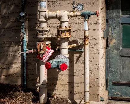
Compression is the default choice for new municipal work in climates with a frost line, where the dry-barrel drain-back design matters more than the seating mechanism; the breakaway flange at grade, the 360° barrel positioning, and the 5¼ in main valve opening are all built around a compression main valve on every current production model [S3][S4][S5]. Slide-gate remains appropriate where an existing system has standardized on the threaded-gate geometry and where crews are trained on the heavier operating torque.
For deeper trench installations or borderline working pressures near the 250 psi class ceiling, compression units with the valve above the seat (opening with pressure) reduce open torque, while slide-gate units with a pilot valve can be considered where line pressure exceeds 150 psig and vibration or chatter on open/close is a documented problem [S2]. Operators specifying new hydrants on a private fire main governed by NFPA 24 should default to UL 246 or FM 1310 listed compression hydrants with a 6 in MJ inlet, two 2½ in NST hose nozzles, and a 4 or 4½ in pumper nozzle [S3].
Comparison: compression vs slide-gate on four decision criteria
On seating mechanism, compression uses a fixed seat with the valve face reciprocating against it, with renewable rubber or bronze sealing faces; slide-gate uses a threaded gate forced into the seat by an internal wedge, generally metal-to-metal [S2].
On debris tolerance, compression is the better performer: lodged rocks tend to score the seat but rarely prevent the valve from re-seating, and the published M&H maintenance guidance lists debris damage to the main valve as the dominant service issue, not gate-jamming [S4]. Slide-gate is more vulnerable to particles getting between the gate and seat because the wedging action amplifies any irregularity.
On operating torque, compression is the lower-torque option because the stem moves a single face on a vertical axis with line pressure either assisting or opposing in a known direction; slide-gate requires the operator to turn the threaded stem through its full travel and then drive the wedge home, producing a noticeably heavier feel [S2].
On standardization, compression is the near-universal default in U.S. municipal and AWWA C502 procurement documents, with explicit compression-type language in vendor submittals, while slide-gate appears mainly in legacy stock and high-pressure derivative specs [S3][S5].
Installation, breakaway flange and drain-back interaction

The choice of main valve type has no effect on the breakaway flange or the dry-barrel drain-back: in both compression and slide-gate units, the main valve sits below the frost line, and when the valve closes, an automatically operated drain valve opens and empties the barrel [S2]. Finish grade should sit roughly 3 in (±3 in) below the break flanges, with a gravel sump at the shoe sized to hold roughly twice the barrel volume, and the auxiliary inlet valve must be thrust-blocked or mechanically restrained to the main [S4].
Operating nut sizing, direction of opening, and nozzle threading are independent of the main valve type, but installers must still verify break system integrity on every unit because vehicular impact shears the breakaway flange at grade to protect the buried valve and underground piping [S3][S4].
Limitations and failure modes
Compression hydrants fail most often from main valve damage caused by debris or from a worn drain valve that allows the barrel to remain partially charged, which then freezes; the main valve itself is repairable in the field on most current production models, which is one reason the design dominates [S4]. Slide-gate hydrants fail most often at the threaded stem-gate interface and at the seat, where metal-to-metal scoring from grit accumulates over decades and is harder to refurbish without pulling the shoe.
Both designs are limited to working pressures inside AWWA C502's scope; sustained operation above 150 psig with chatter or vibration on a standard compression main valve is a signal to step up to a pilot-valve high-pressure hydrant, which equalizes pressure across the main valve through a small center valve and reduces open torque [S2]. Specifiers should also note that NFPA 24 and NFPA 25 govern private hydrant installation and inspection respectively, while AWWA Manual M-17 covers dry-barrel installation and testing details that apply equally to both main valve types [S3].
For adjacent specifying decisions, the ball valve standard selection map covers resilient-seated versus metal-seated trim for comparison, and a typical municipal hydrant run will also include a gate valve on the auxiliary inlet upstream of the hydrant shoe.
Detailed specification references: knife gate valve, and dry type transformer.