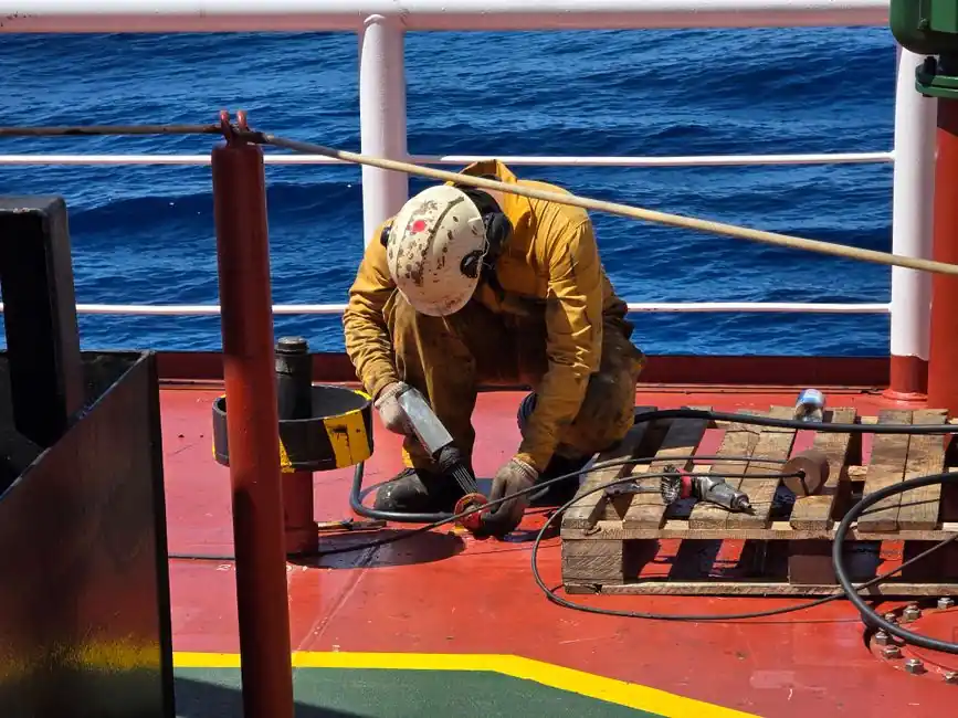
A bellows seal is a precision cartridge, and the field data says roughly three quarters of early failures on rotating equipment trace back to installation, not metallurgy, with sliding O-ring friction, fretting corrosion, and face misalignment the dominant mechanisms [S4]. The job divides cleanly into pre-install verification, mechanical fit-up, and pre-start checks, each with hard acceptance numbers.
This walkthrough covers the sequence used on overhung pumps and similar ANSI/API seal chambers, drawing on John Crane IOM guidance for 1604/2609/3609 series metal bellows cartridges [S1] and the corrosion limits for 316L stainless steel and Inconel 718 bellows stock [S5]. A related reference on flange-side face prep and acceptance sits at Flange Gasket Installation: Procedure, Failure Modes, and Acceptance Checks.
Pre-Install Verification: Shaft, Sleeve, and Chamber Geometry
Before any cartridge is unbagged, the receiving inspection has to confirm the unit is dimensionally right for the chamber; measure the shaft or sleeve OD at the seal position, the stationary-seat OD and thickness, and the available axial chamber space, then identify what is already installed so the replacement matches [S6]. John Crane IOM 1604/2609/3609 also requires the seal chamber housing to be fully disassembled and the shaft/sleeve wiped clean before a cartridge lands in the bore [S1].
Two specific numbers separate a passing install from a leak path: lapped face flatness that supports a fluid film around 0.25 µm between the primary faces, and a surface finish below 1 µm Ra, which is what gets steady-state leakage under roughly 0.1 ml per hour on a healthy seal [S5]. Skipping the wipe-down and pushing a cartridge over a scored sleeve is the single most common cause of secondary seal damage and face chipping during fit-up.
Setting the Cartridge: Flange-Side Groove, Set Screws, and Gland Torque
For welded metal bellows cartridges, the installation position is fixed: the bellows flange end face must seat in the groove on the flange side of the gland, with the bellows itself free to flex axially once the gland is torqued [S3]. John Crane specifies that the gland plate nuts or bolts be securely tightened to the pump-manual value and all screws verified before the cartridge is closed up; do not compress the seal excessively during fit-up, since over-compression bows the faces and lifts them out of the 0.25 µm fluid film range [S1].
After fit-up, hand-turn the shaft to confirm free rotation; any binding, scraping, or tight spot is a sign the cartridge is mis-seated or the gland is over-torqued. On metal bellows service above 200°F in chloride-bearing fluids, material selection has to be locked first: 316L stainless steel bellows are rated for chloride concentrations below 5,000 ppm Cl- at 200°F, while Inconel 718 is the choice for hydrocarbon service up to 800°F [S5]. Specifying the wrong alloy at the install step, not the design step, is the more frequent cause of chloride stress-corrosion cracking seen in the field.
Alignment, Lubrication, and Pre-Start Checks
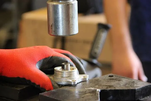
Misalignment is the largest single contributor to accelerated face wear on bellows seals because it loads one side of the lapped pair and starves the other of fluid film [S4]. The corrective action is a coupling alignment check at the pump-driver interface using a laser system, dial indicator, or comparable method, with the final value written to the install record; John Crane IOM puts this check ahead of any seal work in its pre-start list [S1].
Lubrication during assembly is a controlled step, not a habit: a light film of clean assembly lubricant on static O-rings and PTFE wedges only, never on the lapped faces, since any oil on the faces will carbonise under the 0.25 µm film and scratch the seal beyond recovery. Once the cartridge is closed and the gland is torqued, the start sequence is to rotate the shaft by hand, confirm the seal flush, quench, or barrier fluid connections match the piping diagram, then bring the equipment up to a liquid-full condition before energising, because a bellows seal running dry will overheat within seconds and permanently warp the faces [S1].
Failure Traps Specific to Bellows Designs
Two traps catch even experienced crews. First, the dynamic secondary seal: traditional pusher seals carry the spring load through a sliding O-ring on the shaft, and that interface is responsible for about three quarters of early failures in moving-parts service; welded metal bellows eliminate that sliding contact, but only if the bellows is not pre-compressed sideways or twisted during gland fit-up [S5]. Second, the precompression check on flanged metal bellows expansion joints, which shares the same bellows physics: when the ratio of (T_install - T_min) to (T_max - T_min) is 0.15 or less, no precompression is needed, but at 0.16 or above the joint must be precompressed by Rated movement times that ratio, otherwise thermal growth will over-stress the convolutions on first heat-up [S2].
Replacing the seal is almost always the right call when face flatness or finish is outside spec, when the bellows shows corrosion pitting, or when the cartridge has been dry-run. Field-repairing a welded metal bellows by re-lapping the faces is not a sanctioned step; the convolutions and welds have to be evaluated as a unit, and a visibly cracked or work-hardened bellows is a replace, not a reseat.
Sourcing, Standards, and What to Verify on the Datasheet
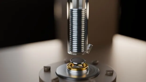
Acceptance on a metal bellows seal datasheet runs on a handful of hard numbers: face flatness supporting a sub-1 µm Ra finish, a fluid film around 0.25 µm, working pressure rated above 1,450 psi (100 bar) on the primary face pair, and bellows alloy selected for the chloride or hydrocarbon envelope of the service [S5]. Bellows assembly materials typically deliver above 90% corrosion resistance across a wide pH range when the annealing procedure is controlled, which is why material traceability, not just the trade name, belongs on the install record [S5].
On the safety side, fluorocarbon and PTFE components must never be burned or incinerated during disposal, since decomposition releases hydrofluoric acid and other highly toxic fumes; wear protective gloves whenever handling used elastomer or PTFE parts [S1]. Storage before install also matters: keep cartridges in a dry, moisture-proof environment, on a flat surface, and never stack them without supports, the same rule that applies to flanged metal bellows expansion joints on the pipe-skid side [S2]. For deeper context on the dynamic secondary seal removal, the article Why Bellows Seals Remove the Dynamic Secondary Seal covers the design rationale behind the welded-bellows construction this install sequence supports.
Track two signals on the next site visit: the alignment reading on the coupling after 24 hours of thermal soak, and the barrier-fluid or seal-flush flow reading at the same time stamp, because drift on either one within the first day is the leading indicator of a bellows seal that was set up within tolerance but not within margin.