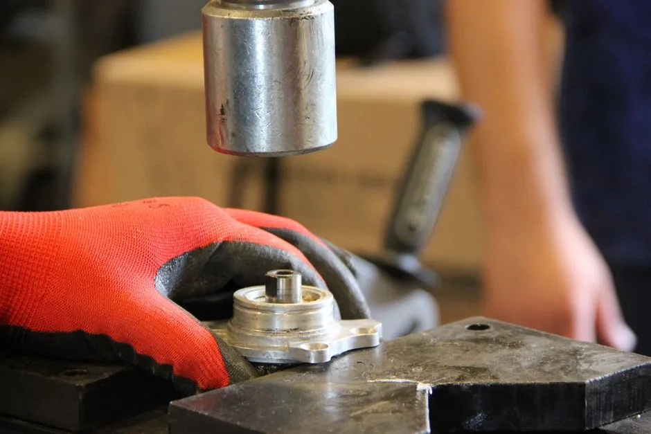
A radial shaft oil seal is a precision interference-fit component: it seals a rotating shaft against a stationary housing by means of a radial lip loaded against the shaft, typically with a garter spring. Because the lip runs on a clearance of a few hundredths of a millimetre, installation defects (cocking, lip nicks, contamination, dry running) cause a disproportionate share of premature failures observed in service.
This article synthesises installation practice from Federal-Mogul/National, SKF, Timken, and industry technical sources, with the goal of giving a maintenance engineer a fault-tree that maps each observed symptom back to a root cause in the install sequence. It complements the broader spec reference on Oil Seal Types and Classifications: A 2026 Spec Reference by focusing on the install step rather than the selection step.
Pre-Install Inspection: Bore, Shaft, and Seal Itself
The seal, shaft, and housing bore must be visually inspected for damage before any fitting tool is picked up: any sharp points, burrs, or nicks on the seal lip will cause leakage, and a single speck of debris under the O.D. will hold the seal off-square [S5]. The same OEM guidance is explicit that the seal O.D. must never be coated with bore sealant, because sealant that squeezes onto the lip contact zone will lift the sealing edge off the shaft [S4].
Spindle preparation on heavy commercial axles follows a defined sequence: clean spindle threads and the keyway, wipe with a lint-free cloth, file any leading-edge burrs, fill chisel marks or gouges with a hardening compound, and smooth with emery cloth before the seal ever touches metal [S4]. When a wear sleeve is present, it is removed with the round end of a ball-peen hammer; a cold chisel is forbidden because it damages the spindle [S4].
Dimensional checks are not optional: the inner diameter, outer diameter, and axial width of the existing groove must be measured against the replacement seal's spec sheet, and the bore should have a 30° chamfer of at least 1 mm on the seal-entry side so the elastomer O.D. is not sheared as the seal enters [S5]. If the shaft shows a flange or keyway in the seal runout zone, a bushing or shaft repair sleeve is required to present a continuous cylindrical surface to the lip [S5].
Tooling: Sleeves, Drivers, and Hammer Selection
For general industrial radial shaft seals, especially silicone-rubber bodied seals, an installation sleeve is mandatory because the seal must enter the bore square without the lip or O.D. contacting the shaft or bore entrance [S2]. The sleeve sits inboard of the seal and supports the O.D. while the seal is tapped or pressed home; without it, the seal cocks and the lip folds.
On commercial wheel ends, the OEM specifies a matched tool per axle type: RD-386 for TN tapered axles and RD-295 for TP straight axles, struck with a 3 to 5 pound hammer until a tone change is heard at the shoulder face [S4]. The tool is rotated 90° to 180° between strikes, then a final 180° rotation with one more strike, so the seal is driven completely and squarely into its seat [S4]. A bearing fitting tool set is the equivalent recommended toolset for general rotating-equipment work [S5].
Hammer weight is a small but specific number: 3 to 5 lb (roughly 1.4 to 2.3 kg), and the seal must be driven until an audible "bottoming" tone change indicates it is fully seated in the bore [S4]. A seal that is under-driven leaks because the O.D. interference is incomplete; an over-driven seal has a deformed lip. Either symptom is rarely fixable without re-work.
Alignment, Lubrication, and the 90° Rule
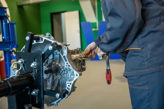
The seal must be installed at 90°, perpendicular to both the shaft and the housing bore, and this is the single most-cited geometric rule across installation literature [S3][S5]. Where the housing face itself is not square to the bore (a common issue with soft aluminium or worn cast housings), the installer must shim or re-machine the housing face, not the seal [S5].
Before the seal touches the shaft, the shaft, sealing lip, and bore are lubricated with system-compatible oil so the elastomer slides on a fluid film rather than dry rubber on steel; this is what prevents the first-rotation dry-running scuff that destroys PTFE and fluoroelastomer lips [S5]. The seal O.D. is lightly oiled, not greased, so it can still slide and self-centre in the bore [S4]. Bore sealant on the O.D. is explicitly forbidden because the squeeze-out reaches the lip contact band [S4].
For split oil seals (used where the shaft cannot be disassembled), the install sequence is different: insert the seal into the bore starting from the split ends, confirm the ends are touching, then compress the leading edge into the bore with a driver that bears only on the seal body, not on the joint [S6]. A mis-aligned split joint is the dominant failure mode for this style, and it almost always traces to the installer not confirming end-to-end contact before driving.
Common Failure Modes and Their Install Root Causes
Symptom to root-cause mapping is the most efficient way to learn from a leaking seal. A seal that leaks immediately on start-up, with no visible external damage, most often has a folded lip from cocking during install, a debris particle under the O.D. holding the seal off-square, or bore sealant squeezed onto the lip contact band [S4][S5]. The corrective action in all three cases is to remove the seal, re-prep the bore and shaft, and re-install with a sleeve; the seal itself is scrapped because the lip geometry is plastically deformed.
A seal that leaks only after a few hours of operation, with the shaft contact band polished but the elastomer intact, most often had the shaft run dry during the first rotation because the lip was not pre-lubricated, or the shaft surface roughness was outside the 0.2 to 0.8 µm Ra range typical for radial lip seals [S5]. The corrective action here is shaft re-finishing or a wear sleeve plus correct pre-lube; the seal is replaced.
A seal that walks axially out of the bore under vibration has either an under-driven O.D. (interference fit incomplete) or a housing face that is not square to the bore, so the dynamic sealing load is partly axial rather than radial [S5]. This is not a repairable condition: the bore must be re-machined or a new housing fitted, and the seal replaced. Trying to stake or glue a walking seal masks the symptom and accelerates bore damage.
Removal: Doing as Little Harm as Possible
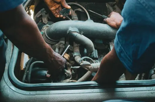
Removal is part of the install cycle, because a re-install into a damaged shaft or bore reproduces the original failure. The recommended method is to avoid full shaft disassembly: drill two small holes through the seal body with an awl and hammer, thread screws or a puller hook into the holes, and draw the seal out axially without prying against the shaft or housing [S5].
If the shaft is scored where the old lip ran, an SKF Speedi-Sleeve or equivalent thin-wall repair sleeve is press-fitted over the scored zone to present a fresh, hardened running surface to the new lip; this is faster and cheaper than re-grinding the shaft in most field conditions [S5]. If the bore is damaged, the housing is re-machined or replaced; do not attempt to compensate for bore damage with sealant, because the O.D. interference fit is what holds the seal in place under pressure [S4].
Once the old seal is out, never re-use it: elastomer memory is lost, the spring is set, and the O.D. has been micro-galled by the bore [S5]. Re-used radial lip seals fail at a much higher rate than new seals even when they look serviceable, so the install kit should always include a fresh seal matched to the bore and shaft measurements.
Selection Criteria Before You Install
Install quality cannot rescue a wrong seal, so a quick selection cross-check is part of the install workflow. The four decision criteria to confirm before driving the seal are: shaft diameter tolerance (typically h11 for radial applications), bore diameter tolerance (H8), axial width match to the housing counterbore, and material compatibility with the fluid and temperature envelope [S5]. Get any of these wrong and even a perfect install will leak or fail prematurely.
For a comparison view across seal styles, the PTFE lip seal versus conventional NBR/FKM spring-loaded seal decision comes down to temperature (PTFE extends the upper limit to roughly 200 °C continuous versus 120 to 150 °C for FKM) and dry-run tolerance (PTFE survives short dry-running events, NBR does not). On the cost side, conventional elastomer seals are typically one-third to one-fifth the unit price of a PTFE unit, so the upgrade only pays back on hot, poorly-lubricated, or chemically aggressive services. The matching sealing washer cost and selection breakdown covers the static-seal cousin of this decision and is useful when a radial and a static seal are being specced into the same assembly.
If the application is a mechanical seal change-out rather than a radial lip seal, the install sequence is different (cleanliness class, face-lapping, set-length verification) and a different article applies; the radial oil seal rules here do not transfer cleanly to that hardware.
Acceptance Criteria and When to Stop, Not Repair
An installed seal passes acceptance when it is fully seated against the bore shoulder (audible tone change from the driver), is square to the bore axis within visual check (no daylight between seal face and housing face), has no visible extrusion of the O.D., and rotates freely by hand without binding or gritty feel [S4]. On commercial wheel ends, Federal-Mogul specifies that the seal be checked for square seating on the shoulder after the driver is removed, and the hub pre-lubed with clean oil before the hubcap is fitted [S4].
Stop-and-replace conditions are clear: any visible nick on the sealing lip, any fold in the lip visible under oblique light, any axial or radial movement of the seal under hand pressure once seated, or any bore/shaft damage observed during pre-install inspection. In these cases the seal is not repairable, the bore/shaft must be brought back to spec first, and only then is a new seal installed with the full pre-lube and sleeve sequence [S4][S5].
Trackable signals to monitor on a unit that has just received a new oil seal include: stable sump or housing temperature over the first 8 hours, no oil film on the housing face outside the dust lip, no change in lubricant level over the first 50 operating hours, and absence of any change in shaft-surface colour at the lip contact band. Any of these drifting is an early indicator that the install was not clean and a controlled re-work is cheaper than an in-service failure.
Spec-level background on the components involved: linear guide.