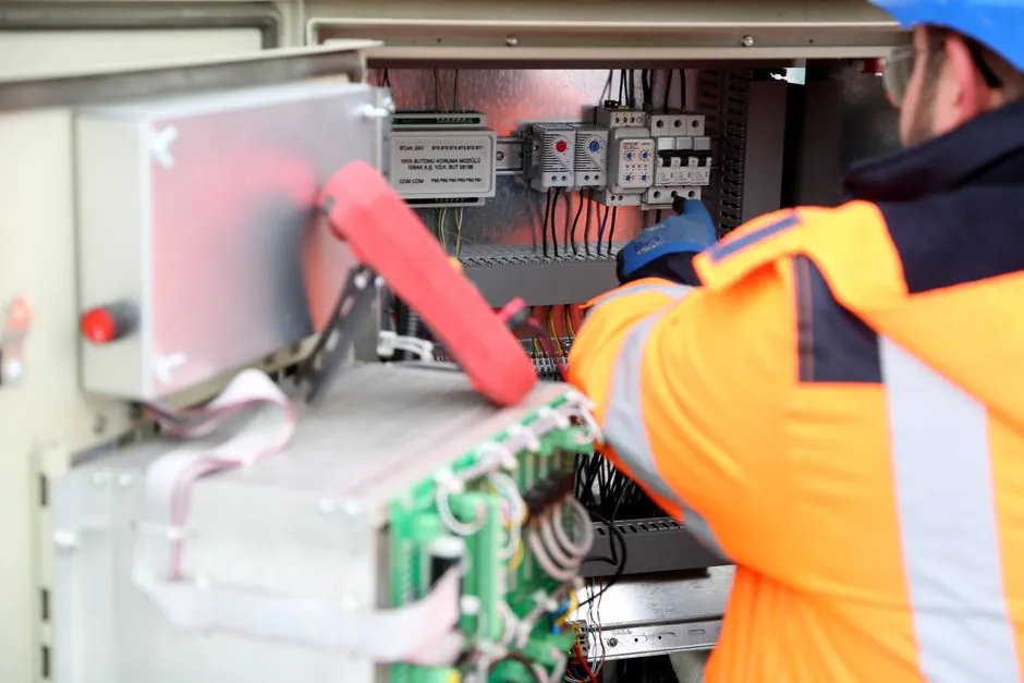
For a 24 VDC supply and a transmitter that needs 12 V minimum to regulate, the maximum allowable loop resistance is (24 - 12) / 0.020 = 600 Ω; that figure is the total series budget, not just the receiver load [S5]. The same arithmetic scaled to a 7.5 V minimum device yields roughly 825 Ω, while a Rosemount 3051CG with a 10.5 V minimum tops out near 587 Ω under the OEM's 43.5 × (V_supply - 10.5) load-line equation [S3][S7]. Every additional series element, including cable copper run, intrinsic-safety barrier, local indicator resistor, and HART filter, consumes part of that 600 Ω budget before the controller input sees a usable 1-5 V signal [S1][S4].
The calculation matters in practice because long cable runs in tank farms, offshore platforms, and 1000 m+ chemical-plant loops are the usual reason a 4-20 mA signal goes non-linear at the top of the range: the transmitter simply cannot hold 20 mA once compliance is exhausted, and the current flattens or saturates [S4][S5]. A working pressure transmitter loop is therefore a budgeting exercise, not just a wiring exercise.
The Core Loop-Resistance Formula and Where It Comes From
The governing expression is R_loop_max = (V_supply - V_min_tx) / I_max, evaluated at 0.020 A (20 mA), because the transmitter is a constant-current sink and the worst-case voltage drop in the loop occurs at full scale [S5]. The compliance voltage concept formalises the same idea: the DC supply must be higher than the sum of all series drops at 20 mA, and any unaccounted drop shrinks the headroom available to the transmitter [S4]. For a generic 4-20 mA device on 24 VDC needing 12 V across its terminals, the budget works out to exactly 600 Ω maximum total, with the 250 Ω receiver load, a 250 Ω HART resistor, and roughly 100 Ω of cable copper all fitting inside that envelope [S1][S5].
Rosemount publishes a slightly different but equivalent form: Maximum Loop Resistance = 43.5 × (Power Supply Voltage - 10.5), derived from the 3051's 10.5 V minimum and a current-loop constant that rounds to 1/0.023; at 24 VDC this returns about 587 Ω, and a 42.4 VDC supply pushes the same device to roughly 1.39 kΩ [S3]. The factor 43.5 is essentially (1 / 0.023), and 0.023 A is the HART-required minimum loop current including the 250 Ω communication resistor drop; using 0.020 in the denominator gives the conservative number stamped on most generic data sheets [S3][S7].
Component-by-Component Voltage Budget
Five elements sit in series in a classic two-wire 4-20 mA loop: the DC power supply, the field wiring (go and return), the transmitter itself, the safety barrier if any, and the receiver load resistor (or analog input module) [S1][S4]. A worked example with a 24 VDC supply, a transmitter rated for 7.5 V minimum, and a 1 km cable run that drops about 20 Ω (0.4 V at 20 mA), gives R_load_max = (24 - 7.5 - 0.4) / 0.02 ≈ 804 Ω, while still leaving more than 230 Ω for HART communication on the same loop [S8]. Substituting a 12 V minimum device shrinks that same 1 km run to about 580 Ω, and any additional 250 Ω indicator resistor or 300 Ω safety barrier consumes the rest of the budget [S5][S8].
Wire resistance is the silent budget killer: a 1 km run of 18 AWG copper (about 21 Ω/km loop) burns roughly 0.42 V at 20 mA, and doubling the distance doubles the drop, so a 2 km run can shave 0.8 V off the transmitter's headroom before any other device is counted [S1][S8]. For differential pressure transmitter installations across a long impulse line plus a long cable run, the same arithmetic applies, and a loop calibrator verification at 20 mA is the fastest field check that compliance has not been violated [S3][S4].
HART and Intrinsic-Safety Constraints on the Budget
HART communication requires a minimum of 230 Ω (typically 250 Ω) in the loop to develop the FSK voltage modulation, and that resistor must sit on the supply side of any measurement point so the handheld communicator can see the AC component [S3][S8]. For IS loops the zener barrier or galvanic isolator adds another 100-300 Ω of series resistance, and the entity parameters of the barrier (V_max, I_max, P_max) further cap the available supply voltage to the safe-side value, often 16 V or 21 V, which then re-enters the same R_loop_max formula with a smaller numerator [S3][S4].
The Rosemount 3051 manual is explicit: a minimum loop resistance of 250 Ω is required to communicate with a Field Communicator, the transmitter operates on 10.5-42.4 VDC with less than 2 percent ripple, and a single supply powering multiple 3051s must hold common-mode impedance below 20 Ω at 1200 Hz [S3]. Those three numbers together define the practical envelope: 250 Ω floor for HART, 587 Ω ceiling at 24 VDC, and a 20 Ω common-mode target for multi-dropped transmitters on a shared PSU [S3].
Diagnostic Bands and Live-Zero Verification
The 4 mA live zero is what lets the controller distinguish a true zero from a broken wire: a healthy loop reads 4.00 mA at LRV, while a faulted loop drops to 0 mA, sits in the 3.6-3.8 mA sensor-fault band, or climbs into the 20.5-22 mA overrange band [S5]. NAMUR NE43 defines the standardised fault bands of 3.6-3.8 mA (low) and 20.5-21.0 mA (high), which is why a properly sized loop with adequate headroom will report a diagnostic current instead of pretending to read zero when the wire is broken [S5]. Verifying that the loop actually reaches 20.00 mA at URV (within 0.1 percent, or 0.02 mA) is the standard commissioning test, and any inability to hit 20 mA at the controller end is direct evidence that the loop resistance budget has been exceeded [S3][S5].
An absolute pressure transmitter loop running at high static pressure and long cable runs is the most common real-world failure mode, because the supply voltage at the transmitter terminals collapses just as the process is pushing the sensor toward URV; the symptom is a non-linear top-of-scale reading that flattens before 20 mA, and the fix is almost always a heavier-gauge cable, a higher supply voltage, or removal of an unneeded series indicator [S3][S8].
Worked Example, Step by Step

Suppose a 24 VDC supply feeds a transmitter with a 12 V minimum, through 500 m of 18 AWG cable (about 10.5 Ω one-way, 21 Ω loop, dropping 0.42 V at 20 mA), an intrinsic-safety barrier at 250 Ω (5.0 V drop at 20 mA), and a 250 Ω receiver/HART resistor. The compliance calculation: usable supply = 24 - 0.42 - 5.0 = 18.58 V, less the 12 V minimum = 6.58 V for the receiver, which at 0.020 A gives a 329 Ω budget for the receiver resistor. The 250 Ω HART resistor fits, and 79 Ω of margin remains, so this loop is buildable; a 600 Ω barrier would fail, because 0.020 × 600 = 12 V would leave nothing for the receiver [S1][S3][S5].
A second case: same 24 V supply, 7.5 V minimum transmitter, no barrier, 1 km of 18 AWG (about 42 Ω loop, 0.84 V drop at 20 mA), and a 250 Ω HART resistor. Usable = 24 - 0.84 - 5.0 = 18.16 V; minus 7.5 V minimum = 10.66 V for the receiver, equating to a 533 Ω ceiling, comfortably above the 250 Ω HART resistor, and leaving 283 Ω of margin for additional devices or future cable repair splices [S5][S8].
Selection Rules and Common Failure Modes
Three rules keep a 4-20 mA loop honest: (1) total series resistance at 20 mA must not exceed R_loop_max; (2) HART requires at least 230-250 Ω on the supply side of the measurement point; (3) the supply voltage at the transmitter terminals, not at the PSU, must stay above V_min_tx under all load and temperature conditions [S3][S4][S5]. Exceeding R_loop_max typically shows up as a non-linear top-of-scale reading, an inability to trim the DAC to 20.00 mA, or a loop that reads correctly at 4 mA but falls short at 20 mA; these are wire-resistance, barrier-resistance, or undersized-PSU symptoms and are almost never transmitter-electronics faults [S3][S7].
For multi-device loops, two practical limits dominate: the IS barrier entity parameters and the maximum allowable resistance for a single 24 V supply, both of which can be confirmed with the OEM load-line equation Maximum Loop Resistance = 43.5 × (V_supply - V_min) before any cable is pulled [S3]. Always cross-check with a loop calibrator substitution test: a mA source at 20.00 mA in place of the transmitter should read 20.00 mA at the controller, and any shortfall is the difference between the budgeted and actual loop resistance [S1][S3].
Trackable signals for the next 3-6 months: NAMUR NE43 field-device conformance at the 3.6-3.8 mA and 20.5-21.0 mA bands, and the rollout of Ethernet-APL (10BASE-T1L) two-wire extensions that share the same 24 VDC trunk topology and will re-use this R_loop_max arithmetic at higher bandwidth; both are mature enough to appear on 2026-vintage pressure transmitter data sheets and barrier certifications [S4][S5].
This topic is covered further in In-Line vs Offline CT for Battery Cells: Throughput, Defect Coverage, and When Each Wins.