
The trade-off on an optical comparator is governed by a fixed physical resolution ceiling: the system can resolve only about 0.0005 to 0.001 inch on the part regardless of which magnification lens is in the turret, so increasing lens power enlarges the image but does not reveal more detail, and it actually exaggerates optical aberrations on small features [S2][S6].
The reason is that resolution on a profile projector is set by the optics and the screen, not by the magnification label on the lens: a 50x lens projects an image fifty times larger than the part, but the blur circle from the lens stays roughly the same physical size in real space, so each grain of fuzz on the silhouette now eats a smaller chunk of the on-screen dimension [S1][S4]. At some point, around 100x on most benchtop comparators, the field of view shrinks to a few millimetres and the operator is left staring at a magnified blur rather than a sharper edge [S2].
How the magnification-to-resolution ratio is calculated
Industry guidance defines per-lens minimum resolution as the system discernible resolution divided by the lens magnification, so a comparator with a 0.0005 inch discernible floor resolves 0.0005 inch at 1x, 0.0001 inch at 5x, 0.00005 inch at 10x on paper, but real working performance stops improving past the lens's diffraction limit [S6]. Dorsey Metrology's own summary treats this ratio as the rule of thumb: divide the system's intrinsic discernible resolution by the magnification in use to get the smallest feature that lens can credibly resolve [S6]. Tooling U's class 351 echoes the same physical model: the on-screen resolution is the product of the mirrors and the magnification lenses, not a function of the part itself [S7].
For a typical horizontal comparator with a 12 to 36 inch screen, that means a 10x lens is generally good down to about 0.001 inch features, 50x down to roughly 0.0002 inch, and 100x near 0.0001 inch, with the qualifier that screen flatness, lens quality, and illumination source all eat into those numbers in practice [S1][S6]. Basler's imaging primer formalises the same physics from the camera side: numerical aperture controls the smallest resolvable feature while the magnification on the monitor is set independently, and the two move in opposite directions as the optical design is changed [S4].
Selection criteria: which comparator configuration fits which feature size
Horizontal comparators (light path runs side-on to the part) suit shaft-mounted components, threaded fasteners, and castings held in a fixture, and they typically support 5x to 100x lenses on a 14 to 30 inch screen, which is enough for the 0.002 to 0.020 inch feature range common in machined hardware [S1]. Vertical comparators (top-down light) suit flat parts such as gaskets, stampings, and thin cross-sections, and they share the same lens stack but lose Z clearance, so any feature more than a few millimetres tall has to be fixtured carefully or measured in sections [S1][S3].
Screen size is a direct lever on usable field of view: a 36 inch screen at 10x shows about 3.6 inches of part in one frame, but the same screen at 100x shows only 0.36 inch, which is why shops running both gears and connectors tend to keep two lens turrets or two comparators rather than re-fixturing for every job [S1]. The Practical Machinist thread on small-gear inspection makes the same point from a different angle: 0.020 inch thick gear teeth with small root radii are at the ragged edge for a comparator, and a home-shop user considering a 14 inch screen Mitutoyo PH-A 350 (over 300 lb) was steered toward stereo microscopes with an XY stage as a more honest measurement path for sub-0.005 inch features [S3].
Where the optical comparator falls short
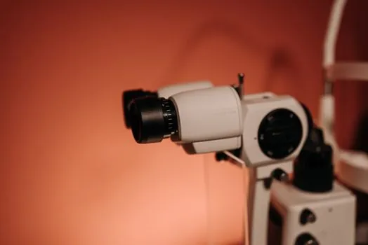
Top-lit features, that is, surfaces that cannot be backlit, are the classic failure mode: with no light passing through the part to cast a clean silhouette, the operator is reduced to tracing edges by hand, and the resolution that looked fine on a backlit profile collapses to whatever the lens can deliver on reflected light [S2]. Hexagon's metrology blog puts it bluntly: a blind hole in a square block cannot be lit from behind, so the edge has to be found manually, and the system offers no numerical data for that edge either, only a visual judgement that does not survive an FDA or AS9100 audit [S2].
The price tag tracks the same limit. Optical comparator systems run from roughly $6,000 for an entry-level benchtop to $138,000 for a large horizontal floor model, and a mid-size shop often lands near $65,000 once screen size, lens sets, and digital readouts are added, money that does not buy you a sharper image past the diffraction limit, only a bigger one [S2]. As a result, sub-0.0005 inch features, anything that needs true surface metrology rather than silhouette comparison, is widely accepted as outside the comparator's working envelope, and shops move that work to video measurement systems, toolmakers' microscopes, or optical comparators with digital edge detection where the sensor does the edge-finding the operator's eye used to do.
Operating procedure that protects resolution
Calibrate the comparator with a certified gauge block or reference standard before every critical run, because the magnification scale, screen geometry, and digital encoder offsets all drift with temperature and handling, and a 0.001 inch measurement built on a sloppy scale is just a number [S5][S2]. Select the lowest magnification that shows the tightest tolerance feature, not the highest, because every lens step past that point gives you a larger but blurrier image and a smaller field of view, which makes part alignment harder, not easier [S5].
Focus and light the part before locking the lens. World of Test's 10-step procedure calls out focus as a separate step from magnification, on purpose: a 50x lens in soft focus will look worse than a 10x lens in hard focus on the same feature, and most operators new to the instrument attribute the softness to the magnification, not to the lamp intensity, condenser position, or stage tilt [S5]. Background lighting is part of the spec envelope: backlit silhouette gives the cleanest edge, top-lit (oblique or coaxial) illumination is acceptable for surface defects only when the lens is matched to the working distance, otherwise the comparator pays for its lamps and light fittings twice, once in the bulb and once in the lost resolution.
Comparison: 10x vs 50x vs 100x on a 14 inch screen
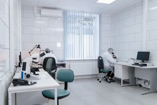
On a typical 14 inch screen comparator with a 0.0005 inch system floor, 10x shows about 1.4 inches of part at roughly 0.001 inch best resolution, fits a single gear tooth or a small stamping, and is the lens most operators should default to. 50x shows about 0.28 inch at roughly 0.0002 inch, good for thread roots and small radii but the part must be re-fixtured and re-zeroed for every feature. 100x shows about 0.14 inch at roughly 0.0001 inch on paper, but lens aberrations, screen flatness, and focus sensitivity make the effective number closer to 0.0003 inch, and the field is so tight that tracking a 0.005 inch edge across the screen is a hand-eye job rather than a measurement [S1][S6]. The decision is not which lens is sharpest, it is which lens keeps the feature, the field of view, and the operator's ability to align the crosshair all inside the same frame.
When to leave the optical comparator on the shelf
Sub-0.001 inch features with tight GD&T, or any feature that cannot be backlit (blind holes, slots on a solid block, surface roughness checks), belong on a video measuring system, a toolmakers' microscope, or a coordinate measuring machine with a vision probe, not on a profile projector, because the comparator is fundamentally a silhouette tool, not a surface tool [S2]. Surface finish and roughness are outside its remit entirely: it can flag a scratch at 50x but cannot quantify Ra or waviness, and any shop trying to use it that way is using the wrong instrument and will be told so during an ISO 9001 or AS9100 audit [S2][S5].
The Practical Machinist gear thread ends in the same place most engineers end up: 0.020 inch thick teeth with a small root radius are doable on a comparator with care, anything below 0.005 inch or anything that needs a true surface measurement is not, and the gear inspection job migrates to a stereo microscope with a Mitutoyo XY DRO for a few thousand dollars, which is cheaper than a used 14 inch comparator and answers the question the comparator cannot [S3]. For shops that already run profile projectors, the honest spec is: use the comparator for silhouette comparison of features 0.005 inch and larger, log the checking and testing apparatus calibration, and route the tight-tolerance work to a different metrology bench.
Trackable signals: monitor whether your 10x lens can still hold 0.001 inch on a calibrated gauge block after six months of shop use, and re-baseline magnification at every lens change rather than trusting the engraved label, since lens-to-lens variation on a used comparator is often larger than the feature you are trying to measure [S5][S6]. A second signal worth watching is temperature: the comparator's 0.0005 inch floor assumes a 20 °C environment, and an unconditioned shop floor can double that number between morning and afternoon, which is why metrology labs, not production cells, are where the tightest optical comparator measurements actually live [S2].
Related analysis: Data Center Steel Structure and Raised Floor Lead Time: 2026 Spec Reality.