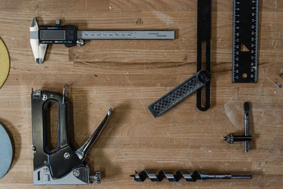
A certified caliper and micrometer program for large castings should treat the hand tool as a calibrated measurement system, not a generic ruler, because cast surfaces, thermal mass, and operator-induced errors routinely push uncertainty past the part tolerance on castings above 100 kg [S3].
This checklist walks through tool selection, calibration evidence, environmental control, datum discipline, and record-keeping that foundries and incoming-inspection teams use before accepting rough or machined castings. Engineers specifying casting tooling for high-tonnage parts need the same evidence as engineers approving the casting mold itself.
Which Hand Tool Goes Where: Caliper vs Micrometer vs Other
Digital calipers with 0.01 mm resolution are suitable for general linear dimensions including overall length, external step dimensions, certain internal features, and wall thickness checks on rough castings where the surface finish does not justify finer resolution [S1]. Calipers are operator-accessible but are flagged as high operator bias and unsuitable for true GD&T features, so they should be limited to simple linear checks on cast surfaces [S3].
Outside micrometers with 0.001 mm resolution are reserved for machined reference faces, bearing journals, and pattern-allowance features where surface finish and geometry allow repeatable anvil contact. Bore gauges, depth micrometers, and height gauges with traceable dial or digital readouts extend the same approach to internal diameters, recesses, and datum-to-feature distances; the basic 150 mm caliper cannot reach these reliably. For a large casting heavier than 1 ton, plan to carry a long-jaw caliper of 300-600 mm, a depth gauge rod, and at least one 0-25 mm or 0-50 mm micrometer set as the minimum kit.
Calibration Evidence the Audit Will Look For
A safety certification style audit of dimensional hand tools expects three documents per gauge: a calibration certificate with measurement uncertainty stated, a traceability statement to a national or accredited laboratory, and a calibration interval policy with the next-due date. The certificate should reference the standard used for calibration (commonly ISO 17025 accredited laboratories follow national equivalents of that standard), the reference standards applied, and the ambient conditions during calibration. [S2]
For a caliper readable to 0.01 mm, typical calibration covers internal, external, and depth jaws at 5 to 10 points across the measuring range, plus parallelism of the jaws and flatness of the depth rod. For a micrometer readable to 0.001 mm, calibration must cover zero error, anvil-flatness, spindle-face parallelism, and a minimum of 5 measurement points across the range; the certificate must show the actual readings versus nominal at each point. Both reports should carry the laboratory accreditation logo, the technician's signature, and a unique certificate number; verbal claims of "factory calibrated" do not meet ISO 9001 or IATF 16949 incoming-inspection requirements [S1].
Environmental and Surface Conditions That Skew the Reading

Castings and hand tools both expand with temperature, and the standard reference is 20 degrees C; a 5 K drift on a 1 m casting produces roughly 0.06 mm of error on steel, which is enough to fail a 0.1 mm tolerance. A cast iron or steel casting lifted directly from a machining cell can run 5-15 K above 20 degrees C, so the inspection plan should include a thermal-soak step before caliper and micrometer work begins. [S1]
Surface condition matters as much as temperature. A rough as-cast surface with Ra above 12.5 micrometers and visible parting-line flash will throw a caliper jaw or micrometer anvil, so the checklist should require local spot-facing, grinding, or measurement on machined witness pads before any micrometer reading. Operator parallelism of the caliper jaws on the feature is the most common source of rejected parts that are actually within tolerance [S3]. Two simple physical checks that catch most operator error: the caliper should slide onto the feature with light, even pressure, and the micrometer ratchet should click three times before the spindle touches the anvil.
Operator Competence and Repeatability Test
A gauge is only as good as the operator, and a basic repeatability test should be run for each inspector on each gauge at least annually. The test uses a calibrated ring, pin, or step block, asks the operator to take 10 readings in random order, and grades them against the gauge resolution and a study guideline (the commonly cited rule of thumb is that the gauge repeatability and reproducibility should consume no more than 10-30 percent of the part tolerance). [S1]
Record the operator's name, the date, the gauge serial number, the reference standard used, and the resulting R&R ratio on the same calibration record. If the operator fails the test, retrain and re-test before allowing that operator to release dimensional results on castings. New operators, agency staff, and anyone returning from a gap of more than six months should re-qualify before their first inspection.
Comparison of Common Hand Tools for Large Castings

Use the comparison below when selecting the right tool for a given feature. The criteria are typical resolution, best-use feature, main risk on castings, and approximate measurement range. [S2]
150-300 mm digital caliper: 0.01 mm resolution, best for general length and external step dimensions, main risk is operator jaw alignment on rough surfaces, range 0-300 mm. Outside micrometer (0-25 mm or 0-50 mm): 0.001 mm resolution, best for machined journals and reference faces, main risk is thermal drift and anvil flatness wear, range 0-50 mm. Bore gauge with dial or digital indicator: 0.001-0.01 mm resolution, best for internal bores above 25 mm, main risk is operator feel and gauge drift, range typically 18-300 mm. Long-jaw caliper 500-1000 mm: 0.01 mm resolution, best for large envelope dimensions on castings above 500 mm, main risk is jaw flex and parallax on long reach, range up to 1 m. Height gauge with surface plate: 0.01 mm or finer with electronic probe, best for datum-to-feature distance on a machined reference face, main risk is surface plate flatness and probe calibration, range 0-600 mm typical.
Datum Discipline and the Drawing Are the Real Specification
Inspection requirements must come from the customer drawing, the purchase order, the approved specification, and the control plan, never from the inspector's judgment, and the same rule applies to large castings as to any other part [S1]. Before measuring, the team should confirm the datum scheme on the drawing, identify the primary, secondary, and tertiary datums, and locate the casting on those datums with a clean, machined reference face or a level inspection table.
If the drawing defines a 0.2 mm position tolerance on a critical bore relative to datum A, the caliper alone cannot verify that, and the checklist should escalate to a coordinate-measuring machine, an optical comparator, or a properly designed functional gauge. The point of the caliper and micrometer checklist is to define what those tools can and cannot do, so a buyer or auditor can see when a measurement is not defensible. For a related requirements-style audit pattern on a different measurement product, see the Pt100 RTD certification checklist for bearing temperature alarms walkthrough, which uses a similar evidence-trace approach.
Records the Inspector Must Sign Before Release

For each inspected casting, the record should list the part number and drawing revision, the heat or lot number, the gauge serial numbers used, the calibration due dates, the ambient temperature at the time of inspection, the operator's name and qualification date, the actual measured values against nominal, the pass or fail decision, and any rework or concession reference. Photos of the as-found measurement setup are increasingly expected by OEM auditors and add a low-cost evidence layer. [S2]
Tie these records back to the casting ladle pour record and the casting aux consumable lot so that a nonconformance can be traced from the casting back to the heat in a single step. Keep the dimensional record, the calibration certificate copies, and the operator qualification sheet in the same folder, and retain them for at least the warranty period of the part, which is commonly seven years for industrial castings and longer for nuclear, marine, or pressure-equipment applications.
Next step for the buyer or auditor: pick one large casting on the shop floor, run this checklist against the caliper and micrometer that measured it, and ask for the gauge certificate, the operator R&R record, and the casting measurement sheet; if any of those three items is missing, the inspection is not auditable, and the casting should be held for a documented decision rather than released on visual acceptance alone.