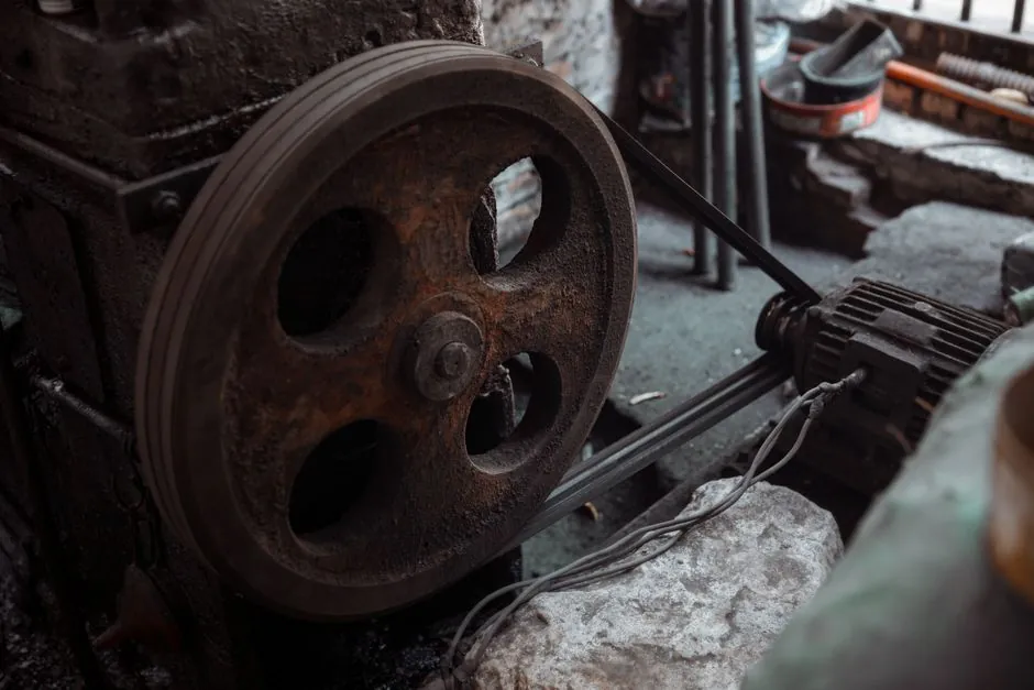
Yes, a helical gear reducer can run at 3,000 rpm input when the selected unit has a documented input-speed rating of at least 3,000 rpm; motor speed alone does not establish suitability [S1][S2].
The decision depends on rated power, reduction ratio, gear geometry, bearing limits, lubrication, sealing, and allowable housing temperature, not simply whether the gearbox uses helical teeth.
What Makes a 3,000 RPM Helical Reducer Valid?
A helical reducer is suitable at 3,000 rpm only if the manufacturer’s rating covers that shaft speed for the specified ratio and duty.
The governing relationship is n_out = n_in / i, where n is shaft speed in rpm and i is the reduction ratio. A 3,000 rpm input at a 10:1 ratio produces approximately 300 rpm output, while a 5:1 ratio produces 600 rpm [S6]. Ratios are normally specified from tooth counts rather than estimated from physical gear diameter [S5].
At 3,000 rpm, check the rated operating speed, service factor, starting torque, shock load, and thermal class of the complete unit. The reducer catalogue must identify 3,000 rpm as an acceptable input condition. A nameplate power of 3 hp or more is not evidence that the bearings, oil film, seals, and gears can tolerate 3,000 rpm [S1][S2].
Helical, Worm, and Parallel-Shaft Alternatives
Helical gears are a practical candidate for 3,000 rpm because a parallel-shaft helical arrangement can be specified as a high-speed drive, provided the unit is individually rated for the operating speed. Helical and spur reducers are also identified as the best candidates for speed-increaser duty within their rated speed envelope [S2][S7].
A worm reducer presents a different selection problem. A technical selection guide asks whether a high-speed 2-pole electric motor operating at 2,800–3,000 rpm can be installed directly on a worm gear reducer [S4]. That does not prohibit every 3,000 rpm worm unit, but it makes a generic worm gearbox an unsuitable substitute for a speed-rated helical reducer.
Worm gears transmit power through longitudinal sliding, so input-speed increases raise sliding velocity, heat generation, lubricant temperature, and wear risk. Those ratio and efficiency figures do not remove the separate input-speed limit.
For a 3,000 rpm input, compare options on rated input speed, load capacity at that speed, thermal margin, and speed-specific bearing and seal suitability. Parallel-shaft helical units are suitable when their rating explicitly permits 3,000 rpm; a standard worm unit is generally the weaker choice unless its maker approves the exact operating point [S2][S4].
Speed Capacity Is More Than Gear Capacity
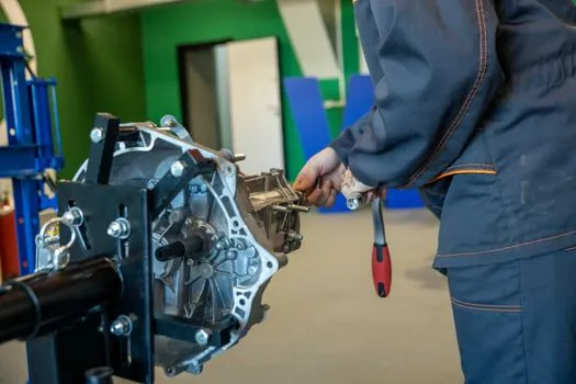
Gear capacity and system speed capacity are not interchangeable. In a speed-increaser example, a 4:1 helical reducer rated for 5 hp and 1,750 rpm input can operate in reverse as a 1:4 increaser at 438 rpm input. The same unit cannot automatically accept 1,750 rpm as the high-speed input because that would produce 7,000 rpm output, outside the operating range of its gears, bearings, lubrication, and seals [S2].
Bearing life is directly affected by shaft speed. Within the speed limit, ball-bearing life can be reduced by the ratio of operating speeds to the reference speed, while operation beyond the bearing limit can cause a substantially larger reduction. At 7,000 rpm output in the cited example, the bearings are likely to exceed their speed limit, and reducing transmitted load does not necessarily compensate [S2].
Oil-lubrated gearboxes also face speed-driven churning losses that are not reduced simply by lowering torque. These losses can raise oil temperature, reduce viscosity, weaken the lubricating film, and exceed the housing’s ability to dissipate heat [S2]. The seal response is equally important because higher shaft-surface speed increases rubbing, seal loss, and oil heating.
Use Cases for High-Speed Helical Inputs
A 3,000 rpm helical input is practical for driven equipment requiring a lower controlled output, including conveyors, fans, pumps, mixers, and packaging machinery, provided the reducer catalogue permits that speed. A 10:1 unit converts 3,000 rpm to approximately 300 rpm, while a 20:1 unit converts it to approximately 150 rpm [S6].
The motor may deliver enough torque after reduction, but the gearbox must also withstand 3,000 rpm at its input shaft, including the fatigue load imposed by the pinion and the dynamic speed-related loads on its bearings.
Helical gearing is not the correct selection for every layout. It suits parallel input and output shafts, while worm, helical-bevel, and helical-hypoid arrangements provide right-angle layouts. A helical gear reducer therefore fits a parallel-axis duty, but shaft orientation alone does not establish its 3,000 rpm capability.
Failure Modes and Selection Checks
Three failures dominate an over-speed installation: lubricant overheating, bearing damage, and loss of gear-mesh capacity.
For helical units, the analogous risks are excessive mesh dynamic loading, bearing speed-limit exceedance, oil churning, seal heating, and thermal overload [S2]. The gear-tooth load effect at elevated pitch-line speed is non-linear, so reducing load may not offset the speed penalty fully [S2].
Before purchase, obtain the model’s rated input speed, allowable output speed, power or torque rating, ratio, service-factor table, bearing configuration, lubricant type, seal limits, and thermal rating. Compare the 3,000 rpm operating point against all six. If the manual or manufacturer does not approve 3,000 rpm, use a higher-rated reducer or change the drive architecture.
Sourcing, Coupling, and Thermal Evidence
The selection file should identify the exact reducer series and ratio, not only “helical gearbox.” A documented 3,000 rpm rating is the primary technical evidence, supported by torque and thermal data for the actual duty cycle [S1][S2]. Tooth-count ratios are preferable to diameter-based estimates when checking a reducer, and a 24-tooth driving a 48-tooth gear produces a 2:1 reduction [S5].
Coupling selection is part of the speed rating. A coupling suitable for 1,800 rpm is not automatically suitable for 3,000 rpm. Its allowable speed, torque, imbalance limits, and operating mode must be checked at the same input condition. Bearings in a variable-speed drive also require separate speed and thermal screening rather than a nominal motor-speed assumption.
For high-speed drivelines, oil lubrication generally supports greater speed and load capability than grease-lubricated gears and bearings, while the selected lubricant viscosity must match the gearbox design [S2]. The bearing-speed and lubrication trade-offs are detailed further in Ball Bearing Speed Limits: Grease Versus Oil.
The direct answer is therefore conditional but firm: a helical gear reducer can run at 3,000 rpm input, but only a manufacturer-approved model with adequate power, ratio-specific capacity, bearing speed margin, lubrication, sealing, and thermal performance. Track the approved input-speed rating and continuous operating temperature for the selected model before releasing the drive for procurement.