
Motor current signature analysis (MCSA) alone is not enough to predict mechanical failures: combining MCSA with vibration analysis raises fault detection coverage from 55-65% (vibration only) and 60-70% (MCSA only) to over 94% on AC induction motors [S2].
Electric motors drive roughly 70% of industrial energy consumption and account for the largest share of unplanned production stoppages, which is why current-only monitoring is being evaluated against multi-modal frameworks in 2026 [S2]. The question for plant engineers is not whether MCSA works, but which of the four primary failure zones (stator windings, rotor bars, bearings, and insulation) a CT clamp at the motor control center can actually see, and which zones it misses until the fault becomes catastrophic.
How MCSA Reads Mechanical Health from a Current Waveform
Every rotating fault modulates the supply current at a characteristic frequency, and Fast Fourier Transform (FFT) analysis of that current exposes the modulation as sidebands around the 50/60 Hz fundamental [S1]. On a three-phase induction motor, broken rotor bars show up as f_s ± 2sf_s sidebands, static eccentricity appears as (1 ± nP/2) × f_s components, and bearing outer/inner race defects produce f_s ± BPFO and f_s ± BPFI sidebands [S1]. CT clamps sample phase current at 10-20 kHz without panel shutdown, then AI models compare sideband amplitudes against fault-frequency equations to assign a fault type and severity score [S1].
Typical lead times from first detectable sideband to functional failure are 4-10 weeks for broken rotor bars, 2-6 weeks for outer race defects, and 6-12 weeks for static eccentricity [S1]. These windows are real, but they exist only because the mechanical fault imposes a periodic torque pulsation on the shaft that the stator current faithfully reflects; if the fault does not modulate torque, the current stays quiet.
What MCSA Catches Well: Electrical and Torque-Modulated Faults
MCSA is the gold standard for electrical-zone failures and for any mechanical fault that modulates air-gap torque. Broken rotor bar degradation shows 60-120 day lead time, air-gap eccentricity (static and dynamic) is detected from sideband asymmetry, and stator shorting / turn-to-turn insulation breakdown shows up as inter-harmonic distortion before the winding fails [S2][S3]. Power-quality issues such as voltage unbalance and harmonic content are also visible in the same current trace, which is why MCSA panels are often specified alongside AC motor monitoring installations on critical assets [S2].
For VFD-driven motors, MCSA additionally catches bearing fluting caused by shaft currents discharging through the raceway, a failure mode that accelerated harmonic converters brought into common plant practice over the last decade [S3]. The same current signal that flags rotor bar cracking also flags driven-equipment anomalies: a choked pump or a jammed conveyor imposes a torque disturbance that shows up as amplitude modulation on the supply current, giving MCSA a limited mechanical-failure reach beyond the motor frame itself [S2].
Where Current Alone Fails: Bearing Race Defects and Coupling Issues
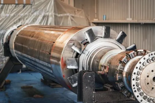
Mechanical faults do not always show up prominently in the motor current signature, so they can be hard to detect by this method alone [S8]. Bearing outer-race and inner-race defects produce a real but weak current modulation compared to the vibration signal at the same fault, because the mechanical path from raceway to stator winding passes through the air-gap flux and gets attenuated, especially on small-frame motors below roughly 5 kW where the signal-to-noise ratio drops sharply [S4][S8].
Shaft misalignment, coupling defects, structural looseness, and rotor imbalance are vibration-domain faults detected at 1x, 2x, and 3x running speed harmonics or at mesh frequencies, and these same faults often produce only a marginal current fingerprint unless they are severe enough to drag a measurable torque change [S2]. Field experience with MCSA on 1-3 week lead-time bearing defects consistently shows that vibration accelerometers mounted on the motor housing catch Stage 2 degradation earlier than any current-based method, which is why reliability programs pair the two [S2][S3]. ISO 10816 vibration severity bands of 2.8 mm/s to 7.1 mm/s depending on motor class remain the established baseline for those mechanical failure modes [S3].
Decision Criteria: When Current Alone Is Enough and When It Is Not
Use MCSA as a standalone when the failure of interest is in the electrical zone (rotor bars, stator windings, air-gap eccentricity) and the motor frame is large enough to produce a clean current spectrum; expect 60-180 day lead time and CT-clamp installation at the MCC with no mechanical intervention [S1][S2]. Use MCSA as a standalone for VFD-driven assets where shaft-current bearing damage and stator winding partial discharge are the dominant failure modes, since vibration analysis on variable-speed drives is complicated by speed-dependent resonance shifts.
Add vibration analysis the moment bearing race life, coupling alignment, or driven-equipment mechanical condition becomes the primary concern, because bearing race defects under roughly Stage 2 produce a current sideband that is below the noise floor of most field installations [S2][S8]. Add infrared thermography when the question is hot-spot identification on the casing or terminal box, with a 10 °C delta above ambient flagged as a predictive indicator [S3]. Add insulation resistance testing (megohmmeter) on a periodic basis, since a winding insulation reading that drops below 1,000 megohms on a new motor is the earliest available signal of moisture or chemical ingress destroying the winding, a fault the current spectrum alone does not expose [S5]. For plant engineers asking whether the investment in continuous drive motor health monitoring pays back, the answer depends on which of the four failure zones dominate the failure history of that specific asset class [S3].
Limits, Failure Modes, and Sourcing
MCSA's effectiveness is hampered by its reliance on reactive responses to malfunctions, and its accuracy in the bearing zone depends heavily on load stability, supply voltage quality, and motor frame size [S4]. Under 20% load, torque-modulated fault signatures can drop below the noise floor even on healthy large-frame motors, which is why MCSA systems often flag "low confidence" alerts in light-load conditions rather than risk false positives [S4]. A 2% winding resistance unbalance between phases, a 5% voltage unbalance, or a 7% current unbalance are the simple ammeter/ohmmeter thresholds that still drive first-pass screening, before any FFT analysis is justified [S5].
Machine-learning classifiers trained on wavelet-decomposed current features are an active research area for pushing bearing-fault detection lead time out of the current-only domain, with Gabor-wavelet and time-frequency methods showing promise in published studies [S4]. For practical sourcing decisions in 2026, the constraint is not algorithm availability but sensor coverage: a single CT clamp at the panel cannot replace a triaxial accelerometer on the housing, and the engineering economics point to multi-modal monitoring for any Class A asset where a stoppage halts the line [S3][S2]. For a related look at how AI is entering adjacent control loops, see Generative AI for PLC Code: Safe Use, Guardrails, and Limits; for the wider 2026 question of whether AI may also close process-control loops on its own, see Can AI Adjust Process Setpoints Without Human Approval in 2026?.
The next trackable signal on this topic is the next revision of ISO 10816 vibration severity thresholds, which governs the cross-check that current-only MCSA results must be benchmarked against for bearing-zone claims. A second signal is any peer-reviewed dataset published in the next 12 months reporting MCSA detection lead time for bearing defects on sub-5 kW motors, since the current 2-6 week outer-race lead-time figure is well established only on larger frames [S1][S4].
Detailed specification references: mechanical seal.