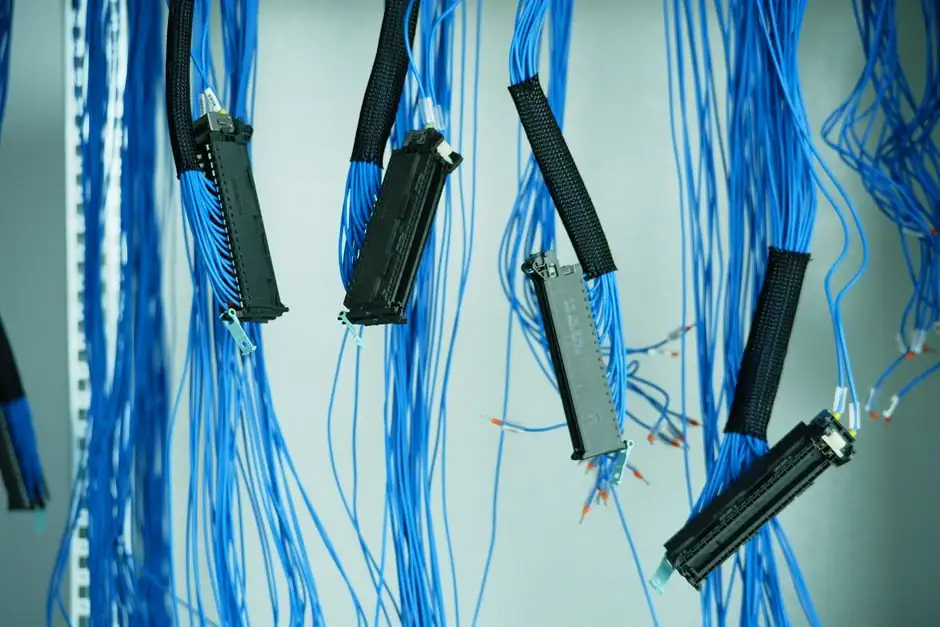
Capacitive sensors only deliver their published resolution if four interface decisions are made correctly during mounting and wiring, otherwise commissioning absorbs hours of bench-tuning that a datasheet cannot flag [S1][S2].
The first decision is mechanical: flush or non-flush. Cylindrical capacitive sensors have precise rules per housing diameter; cubic VariKont-class designs have their own flush, non-flush, and semi-flush rules, and minimum spacing between adjacent sensors must be observed per product series [S1]. For safety-rated variants, the same datasheet rules apply plus a constraint that the sensor must be damped only in the normal installation state, with the target never permitted to pass the sensor undamped during operation [S3].
Mechanical mounting: free zones, target mass, and parallelism
Capacitive sensors respond to a guarded electric field; anything conductive or dielectric within that field acts as a parallel target and shifts the calibration [S2]. Pepperl+Fuchs specifies minimum distances between adjacent sensors and between the sensor and surrounding metal, with the exact value series-dependent on cylindrical and cubic housings [S1]. For Turck capacitive safety sensors, the operating instruction specifies that, depending on type, the sensor must be mounted either flush or non-flush, and for safety-related applications the sensor must be mounted so that it is damped when the installation is in its normal state [S3].
Target parallelism, size, and surface finish each contribute measurable offset. Lion Precision's TechNote LT03-0020 lists parallelism, target flatness, and surface finish as independent error sources, and recommends a flatness within a few micrometres for sub-micron resolution work; the capacitance equation C is proportional to area and dielectric constant, and inversely proportional to gap, so a 10% change in any term changes C by roughly the same percentage [S2].
Electrical interface: 4-20 mA, RS485, IO-Link, or Ethernet
Industrial capacitive sensors ship with analog current or voltage outputs, RS485, IO-Link, or fieldbus interfaces, and the interface choice sets both wiring effort and parameterisation effort [S4][S5]. Micro-Epsilon's compact capacitive displacement sensors expose current and voltage outputs, RS485, Ethernet, and fieldbus options, with the cable and connector assembly designed for fast panel integration [S5].
IO-Link unlocks the bulk of parameter setting remotely. The Allen-Bradley 875F/875L IO-Link capacitive sensor exposes vendor name, vendor ID, device catalog number, and unique device ID over the IO-Link interface, plus all process data and switching thresholds, so commissioning is reduced to assigning the IODD file in the controller rather than turning trimmers on each device [S4]. For bench prototyping or low-volume replacement, Texas Instruments' FDC1004 demonstrates the front-end architecture: a switched-capacitor excitation, sigma-delta ADC, and four CINx channels in a single 4 mm x 4 mm QFN, which is the typical silicon footprint for OEM integration of capacitive displacement measurement [S6].
Calibration, sensitivity, and the bandwidth/resolution trade-off
Factory calibration fixes the sensitivity, expressed in V per unit displacement, with 1.0 V / 100 micrometres a common default [S2]. After installation, the residual errors to budget are offset error, sensitivity error, linearity error, and the combined error band, each of which must be re-measured against the final target and stand-off distance [S2].
Resolution is bandwidth-dependent. Output noise is distributed across a wide frequency range, so filtering at lower bandwidth reduces noise and raises usable resolution; the datasheet resolution value is only valid at the bandwidth the manufacturer states, and specifying 1 kHz resolution while running at 15 kHz output is a common commissioning error [S2]. The same constraint applies when comparing sensors across vendors: a 0.01 micrometre resolution spec at 100 Hz is not equivalent to the same number at 10 kHz.
Target material: conductors, insulators, and dielectric stack-ups
Capacitance scales with the dielectric constant of the material in the gap, so changing the target material changes the output at a fixed gap [S2]. Conductive targets (metal, water, carbon-loaded plastics) produce a high signal because the sensor sees the grounded target as the second plate; insulators (glass, PET, FR4) produce a much smaller signal and require either a ground plane on the back of the target or a higher sensor sensitivity setting [S2].
For multi-layer targets such as plastic film on metal, glass on a touch screen, or paper on a backing roll, the field penetrates multiple dielectrics in series, and the effective capacitance is dominated by the thinnest lowest-permittivity layer. This is the physical reason behind one of the most common commissioning failures: a sensor that worked against a bare metal target gives a flat, non-monotonic output as soon as a 0.5 mm plastic overlay is added. The mitigation, where geometry allows, is to use a guarded or through-hole design rather than a single-ended proximity probe, and to re-zero the offset after the overlay is fitted [S2].
Wiring pitfalls that pass a datasheet check but fail on site
Three wiring mistakes dominate. [S2]
Pepperl+Fuchs specifically calls out that installation accessories and mounting brackets must be selected to preserve the specified free zone, and that the bracket itself must be grounded [S1]. The same logic applies to any retrofit into a magnetic sensor position, where the original bracket may have used the magnetic housing as part of the flux return path, not as a ground reference.
Selection matrix: who capacitive sensors are FOR, and who they are not
Capacitive proximity and displacement sensors are a strong fit for non-contact measurement of position, runout, vibration, and thickness of both conductive and non-conductive targets, including liquid level through a non-metallic container wall, with sub-micron resolution available at low bandwidth [S2][S5]. They are also a fit for IO-Link retrofit projects, because the 875F/875L-style IO-Link capacitive sensor can replace a discrete analog unit and gain remote threshold setting without rewiring the field cable [S4].
They are not a fit for three scenarios. High-temperature targets above roughly 200 degrees Celsius require a cooled standoff or a different technology such as eddy current or LVDT, because the sensor electronics drift and the cable insulation degrades. Dirty, oily, or water-condensing environments wash a non-conductive film onto the active face, which the sensor reads as an offset; an inductive or magnetic sensor tolerates the same contamination better. And applications where the target is smaller than about 80% of the sensor face will see the field wrap around the target, producing a non-linear, range-compressed output [S2].
Commissioning effort: realistic time budgets
For a single-channel bench commissioning against a known target, plan 30 to 60 minutes: 10 minutes for mechanical alignment and free-zone verification, 10 minutes for wiring and earth bonding, 10 minutes for IO-Link or analog parameterisation, and 10 to 30 minutes for sensitivity, offset, and bandwidth adjustment against a reference gauge [S1][S2][S4]. For a multi-point machine retrofit with an unknown dielectric stack-up, plan 90 to 180 minutes per point, dominated by trial-and-error sensitivity setting and re-zero after each fixture change. The most expensive commissioning case in the field is a capacitive displacement sensor swapped onto a former eddy-current bracket, where the bracket earth return and the original sensor bore diameter both have to be corrected before the unit settles to spec.
For related applications with similar interface complexity, see the spec map approach used in servo drive RFQ work for a positioning axis, where the same mechanical, electrical, and signal-chain decisions drive the effort budget. The same pattern shows up in self-priming pump selection for data center cooling loops, where interface compatibility, not headline specs, decides whether commissioning runs to plan or runs over.