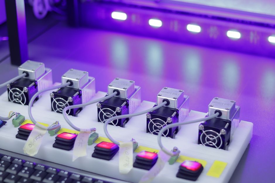
Capacitive proximity sensors detect any material with a dielectric constant above roughly 1.1 by forming an electrostatic field between open capacitor plates, then triggering when the oscillation amplitude crosses a threshold as a target enters that field [S1]. The choice is spec-driven: a non-flush 10 mm unit such as the Pepperl+Fuchs CBN10-F46-E2 with s_n = 10 mm and s_a = 0…7 mm behaves nothing like a flush 15 mm unit in the same product family, even though both are catalogued under "capacitive" [S2][S10].
This guide walks the six gates that actually decide a shortlist — sensing distance, mounting geometry, output type, hysteresis, housing/medium compatibility, and adjustment range — using Pepperl+Fuchs and Rechner Industrie-Elektronik part numbers as the concrete data points [S2][S4][S6][S7][S8][S10]. For an adjacent spec-first reference, see the proximity probe selection criteria for turbomachinery, which follows the same numeric-first approach for eddy-current probes.
Rated vs. Assured Operating Distance: Two Different Numbers on the Same Datasheet
The single most misread spec on a capacitive sensor datasheet is the gap between s_n (rated operating distance, measured against a square 45 mm steel target) and s_a (assured operating distance, the window where detection is guaranteed across temperature, voltage, and manufacturing tolerance) [S2]. Pepperl+Fuchs publishes this pair explicitly because IEC 60947-5-2 testing methodology assumes the standard mild-steel target, while real targets (plastic, glass, liquid, wood) have lower dielectric constants ε_r and therefore trigger at a fraction of s_n.
For non-metallic targets, apply a reduction factor on top of s_a: typical values run ≈0.4–0.6 for most plastics, ≈0.2–0.3 for wood, and ≈0.7–1.0 for water and most aqueous liquids, with the exact figure dependent on electrode geometry and oscillator frequency [S7]. The CBN8-12GH60-E2-V1 with 8 mm non-flush rating is published specifically as "suitable for foodstuff conditions" because its housing and oscillator compensate for the high-ε, high-moisture dielectric loading of wet product [S6].
Flush vs. Non-Flush Mounting: The Geometry Gate That Decides the Housing
Flush-mountable capacitive sensors can be installed in metal at the rated distance without derating; non-flush units require a free dielectric zone around the active face, documented on the datasheet as clearance dimensions B, C, and F [S2]. The CBN10-F46-E2 lists B = 5 mm, C = 20 mm, F = 20 mm / 50 mm — those are the minimum air gaps to any surrounding metal if the unit is to hit s_a = 0…7 mm in the field [S2]. A flush-rated equivalent typically costs 30–50% of its non-flush range because the flush housing contains the field with an internal shield ring.
When panel space is tight and the target is well-grounded metal, a flush unit is the default. When the target is plastic, glass, or liquid passing through a thin non-metallic wall, a non-flush unit reaches further and tolerates the lower ε_r of the wall material [S7]. The CJ10-30GK-WS at 10 mm non-flush and the CJ15U1A2 at 15 mm flush are direct comparators in the Pepperl+Fuchs catalogue and illustrate the geometry-vs-distance trade-off [S4][S10]. For background on the sensing physics, the capacitive sensor reference page covers the oscillator/electrostatic-field mechanism in detail.
Output Topology: 3-Wire PNP vs. 4-Wire DC, and Why It Must Match the Card
The CBN10-F46-E2 ships as 3-wire PNP, NO, at U_B = 10…30 V DC, with reverse-polarity protection — the canonical European DC wiring pattern that sinks into a sourcing input card [S2]. The CJ15U1A2 ships as 4-wire DC for applications that need both NO and NC contacts off one device [S10].
Two failure modes dominate the field: connecting a PNP (sourcing) sensor to an NPN-input card, and back-feeding an AC 2-wire device from a DC supply. Both produce silent no-ops rather than alarms. The datasheet's "output polarity: DC" line and the wiring diagram in the product PDF are the only ground truth — do not infer output type from the housing shape [S2][S10]. For installations that need remote teach-in or parameter data, the same numeric-gate approach scales up to IO-Link capacitive sensors, which embed the same oscillator plus a digital slave interface.
Hysteresis, Switching Frequency, and Adjustment Range
Capacitive sensors are hysteretic by design: the release point sits behind the operate point so the output does not chatter as the target dwells at the threshold. Pepperl+Fuchs publishes H = 1…10 % typ. 5 % of s_n, meaning a 10 mm unit releases roughly 0.5 mm behind the operate point at the typical 5% setting [S2]. Specifying too little hysteresis on a vibrating conveyor or a sloshing liquid target is the most common cause of false pulses in the field.
Switching frequency f on the CBN10-F46-E2 is 0…5 Hz, which is plenty for level detection through a tank wall but is two orders of magnitude too slow for high-speed counting — that duty belongs to inductive sensors on metal targets or magnetic sensors on permanent-magnet targets, neither of which face the dielectric-reduction problem [S2]. The adjustment range, set by the on-board potentiometer on the CJ10-30GK-WS and CJ15U1A2, lets the integrator trim the trigger point across 2…15 mm in the field [S4][S10]. The CBN15-F64-A2-V31 extends this to a 2…15 mm settable range in a flat housing intended for confined-mount installations [S8].
Housing, Media Resistance, and Application Fit
Capacitive sensors are commonly used to detect liquids through non-metallic tank walls, granulate levels in hoppers, paper stack heights, and the presence of food product in hygienic lines — duties where flow sensors and displacement sensors cannot reach. The CBN8-12GH60-E2-V1 is explicitly listed as "resistant against aggressive media" and "suitable for foodstuff conditions", which translates to a stainless-steel housing, an FDA-grade active face, and a sealed cable entry rated for routine clean-in-place chemistry [S6].
Outside food and chemical, capacitive humidity sensors in polymer thin-film form have been used for Bowen-ratio energy-balance flux measurements since at least 2010, with field accuracy improving from ≈3% RH to ≈1.5% RH in commercial modules and power draw of 1–10 mA versus 100–500 mA for psychrometer systems [S3]. That same low-power, no-moving-parts architecture is what makes capacitive the default for battery-powered environmental nodes. For lab-grade trace-gas work, including S-nitrosothiol detection at low micromolar concentrations, custom capacitive cells with functionalised electrodes have been demonstrated in peer-reviewed work [S9]. The interface electronics that turn these nano-farad-scale changes into a usable signal are covered in the Springer reference "Ultra Low Power Capacitive Sensor Interfaces" [S5].
Selection Logic: A Four-Line Shortlist Rule
First, lock the output stage (PNP/NPN, 3-/4-wire, AC/DC) to the PLC card before sizing distance. Second, decide flush or non-flush from the surrounding metal geometry, not from the catalogue's default. Third, apply the dielectric reduction factor on top of s_a for the actual target material — for water and most aqueous liquids this is 0.7–1.0, for plastics 0.4–0.6, for wood 0.2–0.3 [S7]. Fourth, size the hysteresis band 5% typ. for static level detection and 1–2% for slow-moving position detection, but never below the datasheet minimum.
Track for the next specification cycle: vendor migration of potentiometer-set units to IO-Link teach-in (which the Pepperl+Fuchs portfolio already supports across the CJ and CBN lines), and tighter published ε_r correction curves so integrators can stop applying the 30–50% derating as a rule of thumb [S4][S8]. For a price-side companion, the inductive sensor cost guide 2026 lays out the same spec-first logic for the metal-target sibling technology.