
Cartridge valves and subplate-mounted valves perform the same three hydraulic functions, directional control, pressure relief, and flow regulation, yet they integrate into a circuit through fundamentally different mechanical interfaces, with the screw-in cartridge seated inside a machined manifold cavity and the subplate unit bolted to a ported interface plate [S1][S2].
Cartridge cavity geometry typically follows SAE or ISO standard profiles, which is what makes valves from different manufacturers interchangeable inside the same machined block [S1]. Subplate mounting is governed mainly by ISO 4401 for directional-control interfaces, allowing mixed-vendor subplates and valves as long as the port pattern matches [S1][S5].
Definition and Scope of Each Mounting Style
Cartridge valves are self-contained functional elements that screw into a precision-machined cavity inside a manifold block, with no separate body, no sub-bolting, and no extra pipe runs between the valve element and its working ports [S1][S3]. The manifold block itself acts as the housing, and one block can stack relief, check, and flow-control cartridges in a footprint that would otherwise need a stack of discrete valves.
Subplate-mounted valves are complete valve assemblies, most commonly directional-control valves, that bolt onto a separate ported plate. The plate carries the hydraulic ports; the valve can be unbolted and replaced without disturbing the pipework, which is why this arrangement dominates industrial stationary power units, presses, and injection-molding machines [S1][S5][S6].
Footprint, Weight, and Integration Effort
Cartridge construction eliminates the discrete valve body and most of the inter-valve plumbing, which is the structural reason mobile-equipment OEMs (excavators, agricultural machines, cranes, winches) lean heavily on cartridge-based custom manifolds where envelope and mass are binding constraints [S1][S4]. A related engineering reference, the hydraulic valve encyclopedia entry, explains how this integration philosophy reshapes the surrounding manifold design.
Subplate-mounted valves need more cabinet space because each function is a discrete device with its own solenoid, body, and porting. For stationary industrial cabinets, that extra volume is usually an acceptable trade for serviceability [S1]. Sandwich and sectional arrangements built on the same ISO 4401 footprint can stack multiple functions between an inlet and outlet subplate, partially recovering the footprint penalty [S2][S6].
Serviceability and Field Replacement
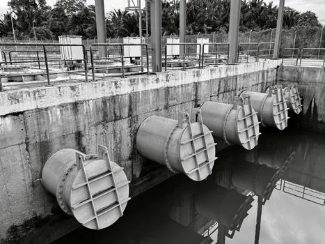
Subplate mounting wins on in-field serviceability: a faulty directional or pressure valve unbolts from the subplate and a replacement drops onto the same port pattern, with no need to disturb pipework or pull a manifold off the machine [S1][S5]. The subplate is essentially the service boundary, and this is also why subplate/sub-base terminology is used interchangeably in industrial hydraulics [S5].
Cartridge replacement requires pulling the cartridge out of its cavity, which on a hot, in-circuit manifold can mean draining a section and dealing with residual pressure. The trade-off is that cartridge swap needs only a hex tool and a clean bench, while subplate replacement often needs the surrounding pipework to be re-torqued and re-leak-tested [S1][S7].
Leakage Paths and Standards Alignment
Cartridge manifolds minimise external leak paths because the working fluid stays inside the manifold block, and the cartridge-to-cavity interface is the only sealing surface, typically an O-ring or backup ring set [S1][S7]. Subplate systems add leak interfaces at the valve-to-subplate joint, the subplate-to-pipe joint, and any sandwich spacers, each of which is a potential external weep point over years of thermal cycling [S1].
The applicable interface standards split cleanly: cartridge cavities track SAE cavity dimensions and the corresponding ISO cartridge standards, while subplate directional-control interfaces follow ISO 4401 (with the older CETOP D03, D05, D07, D08 size codes still in widespread use as the practical naming convention) [S3][S4]. Mixing the two in one circuit is normal; mixing a non-standard cavity with a non-ISO subplate pattern is the configuration that causes field problems [S1][S3].
Decision Matrix: Cartridge vs Subplate on the Criteria That Matter

On four binding criteria, the two mounting styles line up as follows for a 350 bar-class industrial or mobile circuit, the kind of operating pressure where both approaches are common [S4]:
Footprint and mass: cartridges win. The valve element lives inside the manifold body, so a single block can carry relief, check, and flow-control functions in less envelope and less weight than discrete subplate units [S1][S7].
Serviceability and MRO access: subplate wins. Bolted interface, ISO 4401 pattern, and a known service boundary mean a swap does not require pulling the manifold [S1][S5][S6].
External leakage exposure: cartridges win. Fewer joints, fewer gaskets, and the manifold itself acts as the secondary containment [S1].
Standardisation and multi-vendor sourcing: roughly even. Cartridge interchangeability rides on SAE/ISO cavity standards; subplate interchangeability rides on ISO 4401 patterns. Both are mature, but a non-standard cavity or a non-ISO subplate pattern breaks sourcing [S1][S3][S4].
For a quantitative anchor, the S4 reference notes a manual sectional directional control valve rated at 380 lpm nominal flow and 350 bar operating pressure as a representative high-end mobile directional valve, which sets the operating envelope that both cartridge and subplate designs have to serve in modern circuits [S4].
Use-Case Fit: Who Each Style Is For
Cartridge valves are the right pick for OEM-integrated, high-pressure, low-profile systems where size, weight, and assembly speed dominate, including mobile hydraulics on excavators and tractors, custom manifold blocks for truck-mounted crane outriggers and load-handling circuits, and any design where the manifold is owned by the machine builder [S1][S7][S8].
Subplate-mounted valves are the right pick for stationary and industrial systems that prioritise modularity, ease of service, and quick field replacement, including factory presses, injection-molding machines, hydraulic power units, and any plant where a maintenance crew needs to swap a directional or pressure valve without draining half the machine [S1][S5][S6]. They are also the right pick when the circuit is being assembled from standard ISO 4401 (CETOP D03/D05/D07) modules rather than a custom-machined manifold [S3][S4].
Limitations and Failure Modes to Spec Against
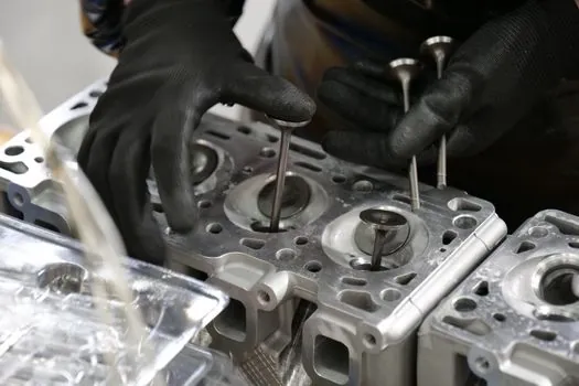
Cartridge systems concentrate risk inside the manifold: a cracked cavity, a contaminated port, or a wrongly specified O-ring kit can take the whole block out of service, not just one function [S1][S7]. Cavity standardisation helps sourcing but does not eliminate the need to qualify a specific cartridge family for a specific fluid cleanliness target (typically ISO 4406 cleanliness codes in the 18/16/13 to 20/18/15 range for general industrial hydraulics, with mobile systems often accepting the higher end).
Subplate systems distribute risk across many joints: every valve-to-subplate interface, every subplate-to-pipe joint, and every sandwich spacer is a candidate for external leakage under thermal cycling and vibration [S1]. The practical mitigation is disciplined torque procedures on the subplate bolts and a defined re-torque interval, not a change of mounting style.
Selection Checklist Before You Commit
Confirm the operating envelope first: maximum pressure (typical industrial ceiling around 350 bar), nominal flow per function, and duty cycle. Cartridge logic elements and pressure-compensated flow regulators cover most of this range in screw-in form [S3].
Decide who owns the manifold: an OEM-owned custom block points to cartridges; a plant-owned standard power unit points to subplate. The wrong choice tends to show up around the six-month mark as a service event, not on day one [S1].
Pin the standards before drawing the schematic: SAE/ISO cavity profile for cartridges, ISO 4401 / CETOP D03/D05/D07 for subplate directional valves, and a stated ISO 4406 fluid cleanliness target. Once those three are fixed, the rest of the bill of materials tends to fall out cleanly [S1][S3][S4].
Trackable signals for the next sourcing cycle: monitor whether your cartridge suppliers publish extended cavitation and pressure-pulsation data for the cavity sizes you actually use (Size 8, 10, 12, 16 are the most common general-industrial sizes), and whether subplate vendors are still holding full ISO 4401 dimensional tolerances or have quietly migrated to a tighter pattern under a proprietary part number [S3]. Either shift will force a requalification pass on the manifold or the spare-valve inventory.
For the relevant spec sheets and selection criteria, see truck mounted concrete pump.
Background reading: Dry Barrel vs Wet Barrel Fire Hydrants: Freeze-Protection Decision Map.