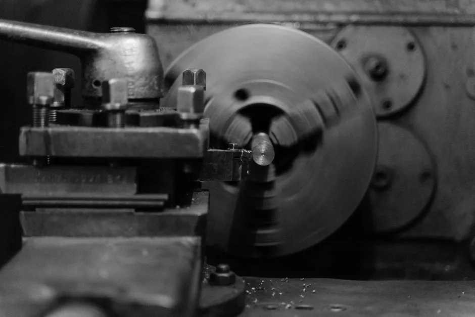
For verifying thread pitch, root radius, and helix angle on a horizontal optical comparator, the workpiece must be secured horizontally between centers or on V-blocks, because the silhouette is only as honest as the way the part is held [S1].
The two fixtures solve different problems: centers lock the axis of rotation to a defined line of centers, while V-blocks just cradle the outside diameter. Choosing wrong costs you either a re-fixture cycle or a measurement that quietly lies about concentricity [S1][S2].
Centers: What They Buy You and What They Cost
Carbide-tipped male centers from J&L Metrology are stocked in 3 in., 5 in., and 8 in. max-working-diameter sizes, with female centers in the same three sizes (AC-2855 / AC-2854 / AC-2856 male; AC-3094 / AC-3095 / AC-3096 female), giving a working envelope that covers most shaft, screw, and threaded-rod inspection jobs [S2].
Centers define a true axis of rotation, so when the shaft is rotated between them on a horizontal comparator, runout, concentricity, and thread helix read against a single reference line rather than a gravity line. That is exactly why both major fixture makers, including OGP, list "staging centers" alongside V-blocks as standard workholding for contour-projector inspection of cylindrical parts [S3]. For automotive threaded fasteners held horizontally on a profile projector, the published application note describes the part sitting between centers on the work stage specifically to expose pitch, root radius, and profile [S5].
Downsides are concrete: you need both ends supported, the centers must be aligned to the comparator's optical axis (a wiggly tailstock reads as a wiggly feature), and the part must have center holes or be centerless-friendly. Long, slender shafts also deflect under the center point load, which is when shops reach for V-blocks instead [S1].
V-Blocks: The Fast, Cheap OD Holder
V-blocks stage a cylindrical part on its outside diameter, so they only need one reference surface and zero center holes. J&L's V-Block Stage line is offered in 1 in., 2 in., 3 in., and 4 in. capacities as singles (AC-2197 / AC-2210 / AC-2216 / AC-2240) and matched pairs (AC-2453 / AC-2454 / AC-2455 / AC-2456), with clamps included in every size, and a separate "Vertically Adjustable V-Block Stage AC-3849" for parts that have to be re-positioned in Z [S2]. Smaller-capacity adjustable V-block-and-clamp fixtures from general metrology suppliers cover diameters from 1/16 in. up to 2 in. for electronics-stage work [S2].
For OD diameter checks, length-overall, and simple profile silhouette, V-blocks are the right tool. They are also the standard holder when you are running a lot of similar cylindrical parts and want to drop, measure, drop-the-next. Matched pairs keep the centerline at a constant height (J&L sells these as "Constant Centerline V-Block AC-2970" and "Universal V-Block Stage AC-3021"), so changing the part size does not force you to re-focus the comparator lens [S2].
The catch: a V-block only locates on the OD, so any runout, concentricity, or thread-helix claim you read off a V-blocked part is contaminated by the part's own OD-to-axis variation. For a ground dowel pin, that is fine; for a turned shoulder shaft with a 0.001 in. concentricity spec, it is not.
Side-by-Side: Centers vs V-Blocks on Four Decision Criteria

Reference axis: centers lock to the part's true rotational axis via center holes, so concentricity and runout are read against a fixed line; V-blocks reference the OD, so the reading mixes OD form with the feature you actually care about [S1][S2].
Setup time and skill: V-blocks win on a shop floor running mixed cylindrical parts, because drop-and-clamp takes seconds and needs no tailstock alignment; centers need both ends registered to the optical axis, which is the slower path but the only honest one for thread and helix work [S1][S3][S5].
Size envelope: carbide-tipped male centers from J&L cover up to 8 in. max working diameter in three jumps (3 / 5 / 8 in.), while V-block stages top out at 4 in. capacity as standard, with matched pairs in the same four sizes [S2].
Best-fit features: thread pitch, root radius, helix angle, and concentricity belong on centers; OD diameter, length, and simple silhouette on V-blocks [S1][S2][S5].
Which One When: A Decision Rule
Use centers when the drawing calls out thread pitch, thread root radius, helix angle, or any concentricity / runout number, and when the part has center holes or can be center-drilled cheaply. The 3 in. male-center pair (AC-2855) covers the majority of small-batch screw and stud work on a horizontal comparator [S2][S5].
Use V-blocks when the spec is OD diameter, length, or general silhouette, when parts are running in a high-mix lot with no center holes, or when the diameter sits inside the 1/16 in. to 4 in. window that standard V-block stages cover [S2][S5]. Matched-pair constant-centerline V-blocks (AC-2970 / AC-3021) are the right pick whenever you are jumping between sizes and do not want to refocus the lens between parts [S2].
For very small cylindrical electronics-style parts, a Vee-notched fingers stage (J&L AC-3818) or a universal base stage with an adjustable V-block (AC-3849) is a better fit than full centers, because center-drilling a 2 mm component is not realistic [S2]. For long, slender shafts that would deflect under center point load, prefer V-blocks and accept the OD-referenced result, or move to a horizontal comparator with a steady-rest-style support if the spec demands it [S1].
Fixture Ecosystem Around the Comparator
OGP groups its standard comparator workholding into three families: staging centers, V-blocks, and a rotary staging vise, all sold as accessories for the Contour Projector and c-vision lines [S3]. Mahr precision vises sit in the same accessory bracket on third-party reseller line cards, with entry pricing around $250 [S6]. The 3 in. wide V-block stage format referenced in surplus listings confirms that 3 in. is the most common comparator-V-block capacity in the used-equipment market, matching J&L's 3 in. stage (AC-2216 / AC-2455) [S2][S4].
Whatever fixture you pick, the rule of thumb is unchanged: the part must be held horizontally between centers or on V-blocks to project an honest shaft profile, and the fixture you choose has to match the feature on the print, not just the shape of the part [S1][S3][S5].
Limits and Failure Modes
Three concrete failure modes to watch for. First, center alignment: if the tailstock center is not on the comparator's optical axis, every feature you measure carries a cosine error that scales with the part's length, so a 0.005 in. misalignment on a 6 in. shaft is not 0.005 in. on the screen [S1][S2].
Second, V-block cleanliness: a chip or burr under the V-seat reads as a diameter error directly, and on matched-pair stages it tilts the centerline, so the constant-centerline promise of AC-2970 / AC-3021 only holds if both seats are clean and undamaged [S2].
Third, OD-to-axis coupling: any feature measured on a V-blocked part is really measuring the OD plus the feature of interest, so for tight concentricity work the answer is to move to centers or to a rotary staging vise, not to argue with the V-block result [S1][S3].
Track these as you qualify the next fixture decision: confirm the working-diameter envelope of the center pair or V-block against your largest part (3 / 5 / 8 in. for J&L centers; 1/16 in. to 4 in. for standard V-blocks), and confirm whether your print calls thread pitch, root radius, helix, or concentricity, because that single field decides centers vs V-blocks [S1][S2].
The underlying component specifications are covered under optical comparator, v belt, and v process line.
Related analysis: Porosity in castings: choosing X-ray radiography vs ultrasonic testing.