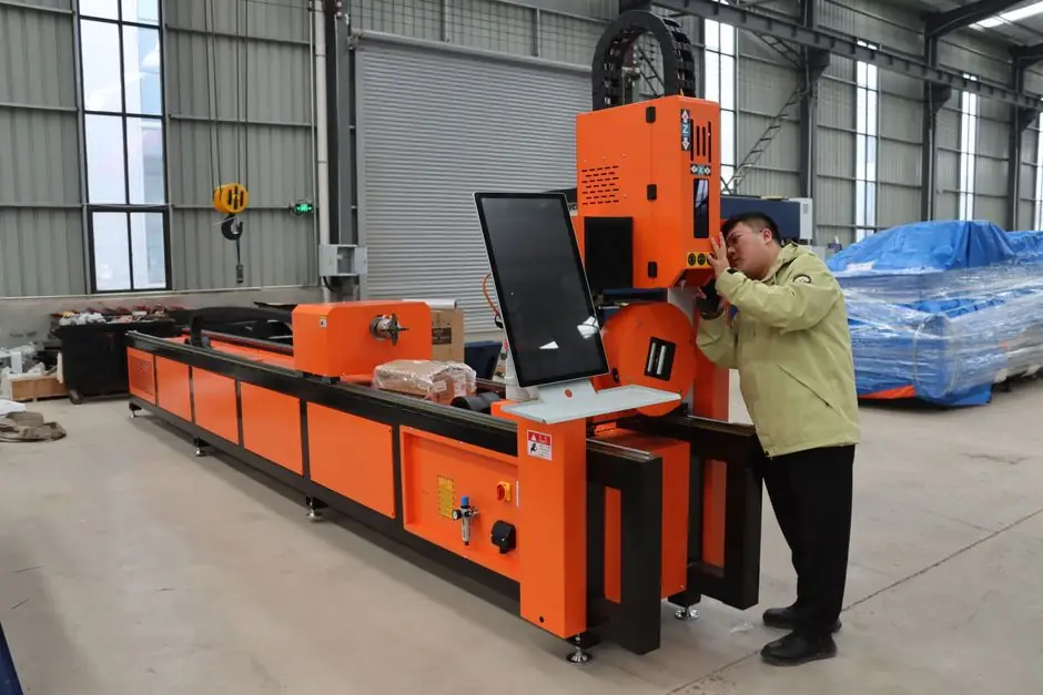
Cardan shaft balancing machines for propeller and drive shafts correct mass unbalance across two correction planes while the rotor runs on roller-bearing pedestals, with residual unbalance on production units typically reported under 10 g·mm/kg per ISO 1940-1 quality grades [S2][S5]. The 2026 product lines from VTM Group, JP Balancing, and Schenck RoTec cover shaft lengths from roughly 0.5 m on car/PHC-class units up to 4700 mm on heavy-truck units, and rotor masses from under 5 kg on small passenger-cardan balancers to 1200 kg on the Schenck 97VK1000 [S1][S2][S5][S6].
Selection pivots on four numbers: rotor mass, shaft length between centers, two-plane correction availability, and balance quality grade (G6.3 / G2.5 / G1) referenced against ISO 1940-1. For propeller shafts on commercial trucks and marine auxiliary drives, the operating grade is commonly G6.3 at service RPM, while high-speed electric-drive propshafts and aerospace-grade propeller assemblies trend toward G2.5 or G1, with corresponding permissible residual tighter than 1 g·mm/kg in some subassemblies [S2][S4].
Working Principle: Two-Plane Dynamic Correction
A cardan shaft balancing machine supports the shaft on two soft-bearing or hard-bearing pedestals whose spindles are driven through a belt or direct coupling, then ramps the rotor through a trial run to measure unbalance vectors on both correction planes [S3]. DE102013101375A1 (Schenck RoTec, granted 2015-02-26) describes a method in which vibration transducers at the pedestals feed a measured unbalance matrix into the evaluation unit, which then computes correction masses and angles for two correction circles (typically at the universal-joint yokes or at dedicated balance flanges) [S3].
PHC-series drive-shaft balancers use rigidly designed brackets that transmit mechanical force with high rigidity and a "permanent calibration" that accepts a large initial unbalance before correction, paired with a high-sensitivity sensor package and a digital man-machine interface [S5]. The two-plane approach matters because a cardan shaft is not a rigid short rotor: its two universal-joint yokes sit at the ends of a tubular midsection, and any residual single-plane correction leaves a couple that excites the second critical mode at highway RPM.
2026 Product Lineup Across Major OEMs
VTM Group's 97VK1000 cardan balancer targets service and repair enterprises handling heavy commercial and industrial shafts, with a stated mass range that places it at the upper end of the VTM lineup alongside the BVI-03-74, which is rated for driveshafts up to 120 kg and 4700 mm long and is positioned for small workshops with mixed truck and light-commercial workloads [S1][S6]. Schenck RoTec's drive-shaft line is positioned as a high-speed, flexible-integration platform with advanced measurement, covering rotor types that include electric armatures, vehicle transmission/axle transmission, and aerospace assemblies, all of which share the same pedestal-and-instrumentation architecture [S2].
JP Balancing's PHC-100 is the entry point for car and light-truck cardan balancing, with a permanent-calibration sensor system and an electrical measuring unit that targets affordable price points for small workshops [S5]. ROKADE Group (India) supplies a cardan-shaft-specific vertical dynamic balancing machine for steel-plant, marine-propeller, and heavy-vehicle applications, configurable for shaft size, weight, and RPM [S4]. The line below summarizes the rough envelope of these machines.
For a cardan shaft balancing machine aimed at 0.5-1.2 m passenger-car propshafts under 20 kg, the JP PHC-100 platform is the typical entry point. For 1.2-2.5 m light-commercial shafts in the 20-80 kg band, the VTM BVI-03-74 class (max 120 kg, max 4700 mm length) is the common pick. For heavy-truck and industrial shafts above 200 kg, the Schenck drive-shaft platform and the 97VK1000 (VTM) take over, with marine propeller shafts and steel-plant drive assemblies typically handled on dedicated heavy-duty vertical balancing machines from ROKADE or comparable builders [S1][S2][S4][S5][S6].
Selection Criteria: Mass, Length, RPM, and Balance Grade
Rotor mass is the first hard limit: PHC-100-class units handle passenger-cardan masses in the 2-20 kg band, while the BVI-03-74 supports up to 120 kg and the 97VK1000 pushes into the multi-hundred-kilogram range, with Schenck's drive-shaft line and 97VK1000 both serving commercial-truck and industrial assemblies that often exceed 200 kg [S1][S5][S6]. Shaft length between pedestals is the second limit; the BVI-03-74's 4700 mm capacity covers the longest single-piece truck propshafts, while most cardan-specific platforms use shorter bed lengths to match a narrower vehicle mix [S6].
Service RPM and the resulting balance grade drive the required residual unbalance. ISO 1940-1 defines grades G4000 (crankshaft drives in slow marine diesel) through G0.4 (gyroscopes, spindles); cardan shafts for road vehicles typically sit at G6.3, while electric-drive propshafts and high-speed industrial shafts trend G2.5 or G1 [S2][S4]. Drive type (belt vs universal-joint drive to the spindle) and the two-plane measurement method (influence-coefficient method vs modal-calibration) are the next two criteria, with the 97VK1000 explicitly engineered for service-shop flexibility on mixed shaft inventories [S1][S3].
Industry Applications and Shaft Mix
Automotive and heavy-vehicle workshops remain the largest installed base: car and light-truck cardan balancing on PHC-class units, heavy-truck and bus on VTM BVI and Schenck-class units, with marine propeller shafts, steel-plant drive assemblies, and industrial rotating shafts forming a secondary but technically demanding segment handled by customizable vertical dynamic balancers [S4][S5][S6].
Schenck's drive-shaft platform explicitly serves the electric-axle and eDrive rotor market, where propshafts in electrified drivetrains spin at higher service RPM than their ICE counterparts and therefore demand tighter balance grades, and the same platform covers aerospace rotor types including jet-engine blades and gear wheels [S2]. For the broader construction machinery and equipment and industrial-transmission ecosystem, cardan balancing machines are commonly installed adjacent to driveline rebuild lines, including shaft collar and yoke stations, where unbalance checks sit between machining and final assembly. The VTM 97VK1000 and Schenck platforms are typical choices for tier-1 service shops and OEM rebuild lines, while PHC-class units dominate the independent aftermarket.
Standards, Tolerances, and Calibration Discipline
ISO 1940-1 is the reference standard for permissible residual unbalance per balance quality grade, and it is the document most service shops cite when grading cardan shafts after correction [S2][S4]. VDI 2060 (ISO balance-grade predecessor) and ISO 9001 calibration discipline are commonly referenced by OEMs that issue traceable certificates, with the dynamic balancing machine class itself defined by ISO 2953 for measurement uncertainty [S2][S3].
Permanent calibration on PHC-class units is a design choice: it lets the operator start with a large initial unbalance and still resolve correction masses, which reduces fixturing time on each shaft but means the machine's calibration must be re-verified annually with a test rotor, typically traceable to a national metrology institute [S5]. The 97VK1000 and BVI-03-74 platforms follow the same annual-recalibration discipline, with the correction-plane indicator calibrated against a master rotor supplied by the OEM [S1][S6]. A common field failure mode is pedestal-roller wear: as the rollers pit, the measurement plane drifts, residual unbalance on the corrected shaft climbs, and a re-calibration against a master rotor is the only reliable field fix [S3][S5].
Limitations, Failure Modes, and Common Pitfalls
Cardan shaft balancing machines assume the rotor behaves as a quasi-rigid body at the test speed: if the test RPM is too close to a bending critical of the shaft, the measurement will read a phantom unbalance that does not represent the in-service condition, and the corrected shaft will still vibrate at operating speed [S3]. On long truck propshafts, the first bending mode typically sits between 1500 and 3000 RPM depending on tube diameter and yoke mass, so the trial speed must be chosen well below the first critical or the two-plane influence-coefficient method will be skewed [S3][S6].
Drive-coupling and universal-joint stiffness are the second pitfall. If the rotor is driven through one of its own universal joints during the trial run, the cyclic velocity variation from the non-constant-velocity joint modulates the measured vibration, and a balancing valve type influence-coefficient correction is no longer valid; a separate spindle drive on the pedestal is the standard fix and is what the PHC, BVI, 97VK1000, and Schenck platforms implement [S1][S2][S5][S6]. A third common pitfall is correcting only one plane to save time on a two-universal-joint shaft: the residual couple unbalance is what excites the cabin-floor and seat-rail vibration at highway RPM on trucks, and the customer returns the shaft within a week [S2][S3][S5].
For lighting equipment and electric lamps on the shop floor, balancing stands are commonly lit with high-CRI lamps and light fittings for reading correction-plane markings, a small but real specification point when retrofitting a balancing bay.
Trackable Signals and Next Specification Nodes
Two trackable signals for the next spec cycle are the formal update of ISO 1940-1 guidance for electric-drive propshafts (which now run at higher service RPM than the 1998-2003 baselines assumed) and the wider adoption of G1-grade acceptance on eDrive rotor assemblies in European and Chinese OEM lines. Watch the Schenck RoTec drive-shaft product page for hard-bearing vs soft-bearing disclosures on new models, and watch the VTM Group catalog for a 2026-2027 successor to the 97VK1000 with a higher mass ceiling and integrated two-plane influence-coefficient reporting. [S1]
Background reading: Inline profile extrusion measurement: 2025-2026 spec landscape and sensor trade-offs.