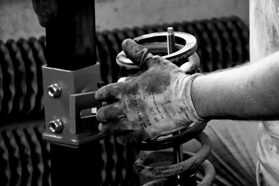
A tapered roller bearing assembly has no factory-fixed axial clearance: the cup and cone are separable, so end play or preload is set only when the bearing is installed on the shaft, per Timken setting literature [S1].
The four components (cone, cup, tapered rollers, cage) and the opposing-pair mounting rule govern how a technician converts axial nut or shim movement into a measurable load zone, and that conversion is the entire point of "setting" the bearing [S2].
Why the Cone-Cup Geometry Forces a Setting Step
The defining feature of a tapered roller bearing is that the cone (inner ring) and cup (outer ring) are not a matched, non-separable unit, which is why mounting force must always be applied to the ring being installed, never through the opposite race [S2]. Because the rollers are frustum-shaped and run on a tapered raceway, the contact angle between the bearing axis and the raceway surface sets the ratio of radial to axial capacity; a steeper angle shifts capacity toward thrust, which is why steep-angle single-row designs show up on pinion shafts rather than wheel hubs [S2].
This geometry also forces the bearing to be mounted in opposing pairs, since a single row can carry axial load in only one direction, and the only variable that ties the pair together is the axial position of one cone relative to the other [S2][S3]. Tolerances on the shaft and housing can therefore be looser than for non-separable bearings, because the setting step absorbs the stack-up rather than the rolling element geometry [S1][S3].
Three Setting Conditions: End Play, Line-to-Line, Preload
EngineersEdge defines the three canonical conditions as end play (axial clearance, load zone under 180°), line-to-line (zero setting, the transition point), and preload (axial interference, load zone over 180°), and explicitly states that preload produces a measurable rolling resistance to shaft rotation [S3]. The "ambient" or cold setting is what the mechanic achieves on the bench, while the operating setting shifts as thermal expansion and elastic deflections load the assembly in service [S3].
Timken's safety note on this exact step is unambiguous: never spin a bearing with compressed air, because rollers can be forcefully expelled; never heat a bearing beyond 300°F; and never cut a tightly fitted cone off the shaft without a guarded press, because tensile stresses in the interference fit can shatter the ring [S1]. For deeper context on how the cone-cup pair sits inside a complete rolling-element assembly, see the roller bearing overview.
Six Published Setting Techniques and When Each Fits
Timken's 5556 brochure lists six field-proven techniques: manual (shims, spacers, or threaded adjustment), preset assemblies, automated setting, Set-Right, Acro-Set, Projecta-Set, and Torque-Set, each converting a different physical input into axial displacement of one cone [S1]. Manual adjustment with shims or spacer sleeves is still the most common shop-floor method for prototype or low-volume work, while torque-set relies on a calibrated nut torque to push the cone along the shaft [S1][S5].
Set-Right is a zero-inventory technique in which bearing setting is obtained merely by assembling the components of a machine to the design geometry, eliminating the need to measure or preset the bearing in a separate operation [S6]. Acro-Set and Projecta-Set use a preloaded reference plug or fixture so that the cone is delivered at a known, repeatable axial position, which is the workhorse approach for volume automotive and industrial gearbox production [S1].
The table below lines the main options up against four decision criteria a process engineer weighs at the spec stage:
Manual shim/spacer adjustment: low tooling cost, moderate accuracy, suited to prototypes and field repair, but slower cycle time and dependent on mechanic feel [S1][S5]. Torque-Set: low tooling cost, accuracy limited by thread friction variability, common on standard machine-tool spindles, but requires a calibrated torque wrench per bearing [S1]. Set-Right: no preset step, accuracy tied entirely to machined spacer lengths, ideal for high-volume gearboxes, but rejects the bearing if housing tolerance drifts [S1][S6]. Acro-Set / Projecta-Set: high accuracy, higher tooling cost, best for volume production of paired bearings, requires a matched reference fixture per part number [S1].
Mounting Sequence and Interference-Fit Discipline
Press the cones onto the shaft and the cups into the housing according to the specified interference fits, then rotate the assembly so the rollers assume their correct position with the large end face in contact with the guide flange [S2][S3]. Mounting force goes on the ring being installed, never through the opposite race, and any hammer-and-bar work should use a mild steel bar (1010 or 1020 grade) to limit high-speed fragment risk if the bar or part fractures [S1][S2].
For a caster or wheel-hub application the field sequence is to install the cup into the wheel bore, drop the cone into the cup, add a flinger washer, then close with the end cap and adjust via a threaded spindle or shim pack to set end play [S7]. Industrial gearboxes and rolling-mill rolls use the same principle but convert axial nut movement into preload against an opposing bearing row, so the same setting decision has very different consequences for life depending on whether the load case is reversing thrust or steady radial [S3][S4].
Common Failure Modes When the Setting Step Goes Wrong
Too little clearance causes overheating because the rolling elements skid instead of rolling at the contact ellipse, while too much clearance lets the rollers skew and accelerates wear on the guide flange [S2]. The boundary between the two regimes sits at line-to-line, which is why preload is specified as a load-zone width (over 180°) rather than as a force number: the engineer is controlling how many rollers share the load at any instant, not how tightly the nut is torqued [S3].
Timken also warns that overheated bearings can ignite explosive atmospheres, so a setting that runs hot in normal service is not just a life problem but a safety problem in dusty or combustible-gas environments such as grain handling, coal processing, or near hydrocarbon vapors [S1]. Whenever preload against an opposing bearing row is the design intent, the assembly must rotate so the rollers align against the guide flange, otherwise the load zone collapses to a single roller and the rated fatigue life is consumed in a fraction of the calculated hours [S3][S4].
Standards, Sourcing, and Trackable Signals
Tapered roller bearing setting is governed by the bearing OEM's installation manual rather than a single ISO or ASME procedure, with Timken, SKF, and other manufacturers each publishing their own torque and shim tables tied to a specific part number [S1][S4]. Timken's published safety envelope is 300°F maximum component temperature, mild-steel (1010/1020) striking tools only, and no compressed-air spinning [S1]. For paired-preload applications such as lathe spindles and gearbox pinions, SKF notes that adjusting one single-row tapered roller bearing against a second and applying a preload is the standard way to achieve a rigid bearing arrangement [S4].
Trackable signals for procurement and maintenance teams: the next observable node is the bearing temperature 30-60 minutes into a loaded run, which should stabilize within 10-20°C above ambient if the ambient setting was chosen correctly; a continuous climb indicates either insufficient end play or lube starvation [S3]. A second signal is the vibration spectrum at running speed, where elevated levels at outer-race or inner-race defect frequencies usually trace back to a setting that was either too tight (overload on a small load zone) or too loose (roller skew and raceway spalling) [S3][S4]. For related spec-trade-off work on adjacent mechanical components, see the alternating-torque sizing rules reference.
Detailed specification references: locking assembly.