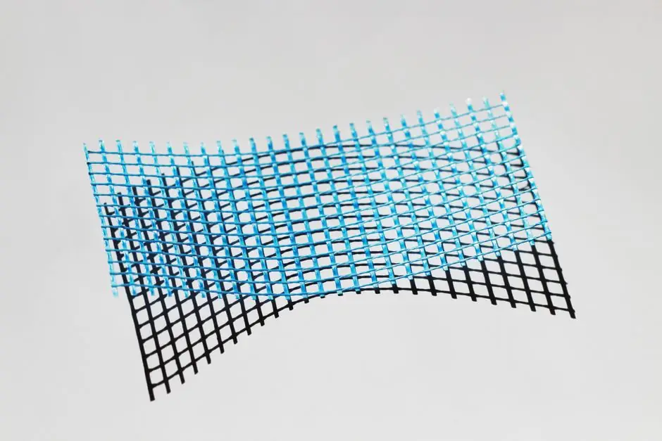
The comparison covers fiber length, fiber placement, printer hardware, and direction-based mechanical behavior for chopped and continuous carbon fiber filament systems [S3].
Stiffness Gap and Load Direction
Continuous carbon fiber provides directional reinforcement because long strands carry load along their direction, whereas chopped carbon fiber provides distributed reinforcement through the extruded bead [S3].
Chopped fiber remains useful because reinforcement is distributed through the extruded bead. It raises stiffness across the printed material, but it cannot reproduce the long, aligned reinforcement architecture of a continuous-fiber laminate [S1][S3].
Decision Matrix for Material Selection
Choose continuous CF when stiffness, low mass, and a known load direction justify dedicated equipment and fiber routing. Choose chopped CF when one material must form the entire geometry, the load is multidirectional, and a standard material-extrusion workflow is more important than peak structural performance [S1][S3].
The comparison is valid only when the material grade, fiber content, test method, print orientation, and reinforcement volume are held consistent. “Carbon-fiber reinforced” on a spool label is not itself a stiffness specification [S2][S3].
Printer and Workflow Requirements

Chopped CF normally retains a familiar single-material extrusion workflow, although the abrasive filament requires a hardened nozzle and suitable extrusion temperatures. Continuous carbon fiber is usually placed through a dedicated fiber path and requires compatible hardware [S3].
Continuous reinforcement can be placed as long strands in selected layers, and its mechanical behavior depends on the direction of the reinforcement [S3].
The two systems should not be compared on filament diameter alone. Chopped fiber is compounded into the thermoplastic before extrusion, whereas continuous carbon is introduced as long strands into a compatible matrix during printing [S1][S3].
Thermal Limits and Dimensional Behavior
Chopped carbon fiber makes the printed material stiffer and causes it to shrink less than the corresponding unfilled material [S2].
Fiber architecture helps explain the stiffness difference: continuous strands provide directional reinforcement, while chopped fibers provide distributed reinforcement through the extruded bead [S3].
Use Cases and Failure Boundaries

Use chopped CF for housings, fixtures, printer parts, jigs, visual prototypes, and geometry that benefits from a stiffer, matte technical material without complex reinforcement routing. Its entire printed body receives reinforcement, making it more forgiving for general geometry [S3][S5].
Use continuous CF for thin stiff arms, functional brackets, load-bearing fixtures, and end-use tooling where the dominant force can be aligned with continuous paths. The directional architecture is an advantage only when the load path and print orientation are designed together [S1][S3].
Do not select continuous CF for an isotropic stiffness requirement, a part with uncontrolled multidirectional loads, or a production system lacking fiber-routing capability.
Verify the supplier’s declared fiber length or architecture, test orientation, specimen dimensions, print settings, moisture conditioning, and tensile or flexural method. Carbon fiber performs strongly in tension, but tensile strength alone does not establish flexural, impact, or interlaminar performance [S2].
Qualification and Test Evidence
A procurement decision should use comparable coupon data rather than storefront claims. Request at least tensile modulus, flexural modulus, tensile strength, flexural strength, elongation at break, density, and heat-deflection temperature for the exact filament grade and print orientation [S3].
For continuous CF, also document reinforcement path, fiber volume fraction, number of layers or strands, and variability between parts. For chopped CF, document nominal fiber length, fiber percentage, matrix polymer, nozzle type, and drying conditions [S1][S2][S3].
For related selection context, the comparison between CF-filled and GF-filled nylon filament stiffness helps distinguish carbon reinforcement from glass reinforcement when the base matrix remains nylon.
Use a representative load case to approve either material: define load magnitude and direction, allowable deflection, geometry, print orientation, and the fiber-routing strategy, then validate coupons and production parts under the intended service temperature.