
A contour measuring machine is a stylus-traced form instrument that records macro geometry and, on combined units, micro roughness (Ra, Rz) in one sweep, with premium systems resolving form deviations to nanometre level for ISO 1101 profile-tolerance verification [S4][S5].
Selection is not about brand loyalty; it is about matching traverse range, Z resolution, axis count, and tip geometry to the workpiece, and binding the lot to a defensible calibration chain. The mainstream categories you will see on a 2026 shortlist are benchtop manual units, motorised 2D systems, CNC contour/roughness hybrids, and large-format form/roundness platforms that bridge into the contour measuring machine duty envelope [S2][S3].
What the instrument actually does, and what it does not
A contour measuring system traces a fine diamond-tipped stylus across a workpiece surface and logs the resulting profile; combined models also return Ra/Rz roughness in the same trace, while contour-only models such as the Mitutoyo Contracer line drop the roughness channel [S4]. The tool is the industry workhorse for ISO 1101 profile-of-surface tolerance verification on aerospace turbine blades, automotive cam profiles, gear teeth, medical implants, and precision-moulded parts where macro form must be captured with micron-level accuracy [S4].
It is not a replacement for a vision measuring machine on small 2D features, nor for a coordinate measuring machine on free-form 3D surfaces; profile projectors see only a 2D silhouette, and touch-probe CMMs take discrete points and struggle with continuous profile tolerances, which is why stylus tracing is preferred for complex profile work [S4].
Four sizing variables that drive 80% of the decision
Traverse range is the first gate: entry benchtop units typically cover roughly 50-100 mm X by 50 mm Z, mid-range CNC systems extend to 200-300 mm X, and large-format units such as the ZEISS RONDCOM 73A / 76A push measuring range up to handle heavy workpieces [S3]. Under-specifying the X traverse is the most common rework; over-specifying it by a factor of three is the most common wasted CapEx.
Z resolution and accuracy separate manual from metrology-grade: combined CNC systems like the Mitutoyo Formtracer Extreme CS-H5000CNC and ZEISS SURFCOM NEX target the low nanometre / sub-micrometre Z band needed for tight profile tolerances, while manual entry units sit one order of magnitude looser [S4][S5]. Stylus tip radius is the third variable, with 2 µm, 5 µm, and 10 µm tips traded off against surface finish, and a worn tip is the single biggest source of false failures, which is why the practitioner razor-blade test for tip condition is still the cheapest diagnostic on the shop floor [S4].
Axis count and automation complete the picture: 1D manual tracers, 2D motorised units (typical ZEISS SURFCOM NEX 040/030 class), and full CNC contour + roughness hybrids differ by an order of magnitude in throughput, and the deciding factor is usually sample volume rather than part size [S3][S5].
Option-by-option comparison on buyer-critical criteria
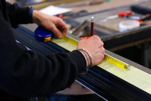
Using publicly described product lines, four option classes can be lined up against four criteria: traverse range, Z resolution class, automation level, and indicative fit. The table below is a selection aid, not a price quote. [S3]
Manual benchtop (e.g. Mitutoyo Contracer CV-2100 class): X traverse roughly 50 mm, Z resolution in the sub-µm band, 1D tracing, fit for toolroom spot checks and low-volume QC [S4][S5]. Motorised 2D systems (ZEISS SURFCOM NEX 040/030 class, SURFCOM 1400 class): X traverse roughly 50-100 mm, Z resolution at the nanometre level, 2D motorised, fit for production-line QA on small precision parts [S3][S5]. CNC contour + roughness hybrids (Mitutoyo Formtracer Extreme CS-H5000CNC class): X traverse 200 mm and up, nanometre-class Z, full CNC, fit for aerospace blade and medical implant certification [S4]. Large-format form/roundness platforms (ZEISS RONDCOM 73A / 76A class, RONDCOM NEX): large measuring range for heavy workpieces, roundness-class accuracy, fit for shafts, bearing rings, and large turned components rather than narrow-tolerance profile work [S3].
The honest takeaway: a buyer who needs nanometre Z on a 250 mm blade profile should not be shortlisting a manual benchtop unit, and a buyer with ten small stampings a shift should not be paying for a CNC hybrid. The mid-band motorised 2D class is the workhorse for most general QA labs in 2026 [S3][S4][S5].
Standards, calibration, and the audit trail you will be asked for
Two standards govern most contour / form programmes in 2026: ISO 1101 for geometric tolerancing of profile, and JIS B 7451 for the contour-measuring instrument itself, which is the calibration chain buyers should expect the vendor to trace [S4]. Resolution is meaningless without a written calibration path back to a national standard through a certified stylus and reference artefact.
On the metrology side, the related roundness and form platforms (ZEISS RONDCOM 73A / 76A, RONDCOM NEX, Contourecord 1600G) are now described as supporting transfer of contour, roundness, and roughness data into a single quality data context via ZEISS PiWeb, which is the audit-trail piece buyers in regulated industries will want confirmed before signing [S3]. For buyers crossing over from CMM work, it is worth noting that coordinate measuring machine sizing and contour sizing share vocabulary but not resolution targets, and conflating them is a common RFQ error.
Who should pick which option, and who should not

Pick a manual benchtop unit if your shop runs low-volume toolroom checks, your parts fit inside roughly 50 mm X, and your tolerance band is in the micrometre rather than sub-micrometre class; do not pick it if you are signing aerospace PPAP or medical-implant dossiers [S4][S5]. Pick a motorised 2D system if your mix is small-to-medium precision parts at moderate volume and you need traceable roughness plus contour in one report; this is the mainstream 2026 default for general QA [S3][S5].
Pick a CNC contour + roughness hybrid if your programme requires unattended multi-feature scans on blades, gears, or moulded medical parts, and your calibration regime can defend nanometre Z; do not pick it if your operators are not trained on CNC metrology software, because utilisation collapses fast on these units [S4]. Pick a large-format form/roundness platform if the workpiece is heavy, shaft-like, or bearing-ring-like and your tolerances are roundness and cylindricity rather than tight profile; for buyers also evaluating roughness-only or CMM-heavy workflows, it is worth reading the related guidance on roundness tester selection specs, types, and buyer pitfalls before locking the shortlist.
Limitations, failure modes, and what the brochures do not say
Stylus tip wear is the dominant failure mode; even a slightly chipped 5 µm tip will print as a false step on a tight radius, and the cheap field defence is the practitioner razor-blade test described in mainstream contour guides [S4]. Vibration and thermal drift are the next two, with nanometre-class Z only valid in a metrology-room environment, not on a shop floor next to a press, which is why CNC hybrid installations are usually specified into a controlled cell rather than a general workshop [S3][S4].
The third limitation is geometric: a stylus tracer is fundamentally a 2D line-trace instrument, so a feature that needs true 3D form verification belongs on a vision measuring machine with multi-angle optics or on a scanning CMM, not on a contour unit regardless of how expensive the contour unit is [S1][S4]. The fourth is software lock-in: combined contour + roughness data and PiWeb-class centralised reporting are real productivity gains but they also commit the lab to a vendor ecosystem for calibration artefacts and styli, which is a five-year TCO decision rather than a one-line spec [S3].
Shortlist logic and trackable signals
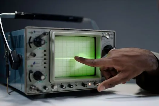
A defensible 2026 shortlist starts with three gates: workpiece X traverse (with 20% headroom), Z resolution class (matched to your tightest ISO 1101 profile call-out), and the calibration chain (JIS B 7451 with a traceable stylus set). Filter the four option classes above against those three gates, then layer in automation only if sample volume justifies it; that ordering alone removes most of the mis-specs the industry reports [S4][S5].
For buyers in chemical or process-plant adjacent QA, the related spec-first map on contour measuring machines for chemical processing duty walks the same gates under harsher corrosion and ambient constraints. Two signals to track over the next two quarters: vendor releases pushing CNC contour + roughness into smaller footprints, and tighter integration of contour data into centralised quality-data platforms such as ZEISS PiWeb, both of which are visible in 2026 OEM literature [S3][S5].
Spec-level background on the components involved: linear guide.