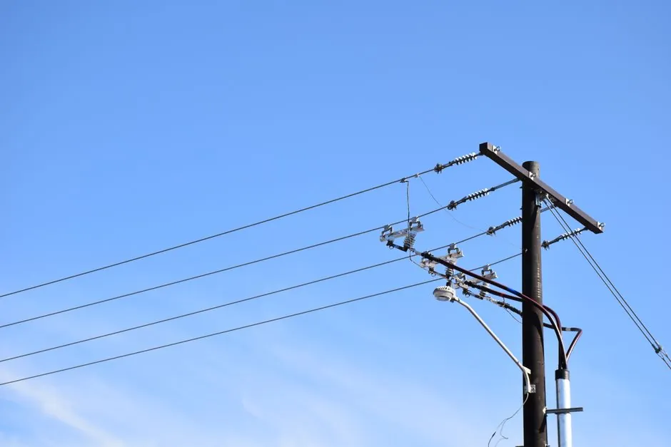
A rigid copper busbar is generally the better high-current busway conductor above roughly 630 A because it replaces parallel cable sets with one phase conductor per enclosure [S1].
The comparison applies to copper busbar trunking, insulated power cable, and conventional bus duct, with the cited excerpt identifying roughly 630 A as the point past which a single cable set can no longer carry the load and parallel cable sets are used [S1].
Selection thresholds and system scope
The practical crossover is approximately 630 A for one standard cable set; beyond that level, designers commonly need 4, 6, or 8 cables per phase, subject to the applicable installation rules [S1]. This is an engineering crossover rather than a universal current limit, because cable size, insulation, conductor material, installation method, ambient temperature, and grouping affect the result.
A busbar is a metallic strip, bar, or solid conductor, while busbar trunking is a prefabricated conductor system installed in an enclosure [S2][S4]. Bus duct generally describes an enclosed run between major equipment, such as a transformer and switchgear, whereas busway normally describes a distribution run with tap-off units [S1].
The cited material states that past roughly 630 A, a single cable set can no longer carry the load and designers therefore use parallel cable sets [S1].
Copper busbar and cable compared
Copper busbar offers a compact rigid path, lower impedance, modular bolted sections, and fewer termination points, while cable offers flexible routing and often lower initial material cost [S1][S5]. The supplied material identifies lower voltage drop over distances and compact design as advantages of copper busbar over traditional cables [S5].
On installed space, copper busbar wins where a single enclosure replaces multiple cable trays and supports; cable wins where the route has numerous bends, small radius changes, or restricted access. On installation labor, bolted busway sections generally replace repeated cable pulls, cleats, and terminations, while cable may be quicker for short, simple feeders [S1][S5].
For maintenance, the busway has fewer joints and termination points to inspect, but its bolted joints still require prescribed tightening and inspection. Copper busbar also permits expansion through tap-off units at designated positions, whereas a new cable route is generally needed to add a remote load [S1][S5].
This comparison uses copper material as the conductor basis.
Electrical and thermal behavior
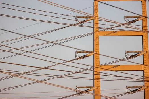
Their lower impedance over the installed route can reduce voltage drop, although the final calculation still depends on conductor dimensions, run length, joint design, temperature, and fault duty [S5].
Cable performance changes with the number of parallel conductors because grouped cables heat one another and require a grouping derating; adding a sixth cable does not add one sixth of the available capacity [S1]. Parallel conductors also share current imperfectly when small differences in loop length or termination resistance exist, so the distribution of load requires verification throughout the installed life [S1].
A completed busway still requires an engineered enclosure because touch protection, phase segregation, insulation coordination, and fault withstand are system-level requirements, not properties of the metal alone [S1].
Where busbar and cable fit
Busbar is appropriate for switchgear rooms, substations, production lines, data centers, EV charging systems, and other high-current distribution routes where compactness, modularity, or future tap-offs justify the system cost [S1][S2].
Cable remains the sensible choice below the practical high-current crossover, for short feeders, equipment alignments with unavoidable offsets, routes requiring sharp directional changes, and installations where a busway route cannot fit the building or where minimum purchase cost dominates [S1][S5]. Flexible conductors also remain necessary inside equipment for transformer or generator connections even when the main distribution route uses busbar.
For a power-distribution backbone with repeated takeoffs, copper busway is normally the stronger engineering choice. For an isolated transformer-to-panel run with no expansion requirement, compare the complete installed design rather than assuming busbar has lower lifecycle cost.
Material, joint, and installation constraints
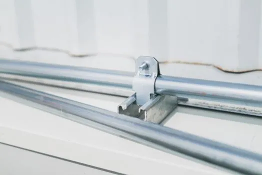
A practical cable alternative above 630 A can require 18 pulls for six conductors per phase across three phases, 18 sets of cleats, and 36 terminations [S1]. That connection count increases installation time and creates more opportunities for phasing, torque, and termination faults than a factory-assembled busway with fixed phase positions [S1].
Copper busbars are available in rigid, flexible, laminated, and insulated configurations, but the selected construction must match movement, insulation, joint, and environmental requirements [S2][S3]. The thickness decision should be based on ampacity, temperature rise, voltage drop, mechanical support, and short-circuit withstand, not on current alone; copper busbar thickness sets current capacity expands that calculation.
Procurement and verification criteria
Specify the system rating, conductor material, busbar dimensions, enclosure construction, phase arrangement, joint type, tap-off provisions, ambient design conditions, and short-circuit withstand before comparing commercial systems [S1][S2]. IEC 61439-6 governs the construction and design verification of busbar trunking systems, while IEC 61439 is identified as the relevant busbar product framework [S1][S5].
For cable, the comparison should include conductor size, number of parallel runs per phase, insulation and installation method, grouping derating, conduit or tray fill, route length, voltage drop, and short-circuit protection [S1]. For busbar, include the type-tested current rating, temperature rise, enclosure, joint design, mechanical strength, feeder accessibility, and every required tap-off [S1][S2].
Do not award busbar a lower total cost without counting trays, supports, installation labor, terminations, inspection time, and anticipated load changes. Conversely, do not award cable a lower cost without counting derating, copper quantity, tray area, and the installation labor caused by parallel runs [S1][S5].
The next engineering checkpoint is a side-by-side loss and installed-cost study using the actual route length, 6,300 A maximum system context, proposed current, ambient temperature, and required expansion; retain the busway option when the load exceeds the practical single cable-set capability or requires planned tap-offs.