
A copper busbar 100 mm wide and 10 mm thick has a preliminary current-carrying capacity of 1,200 A when calculated at 1.2 A/mm² of cross-sectional area [S1].
The calculation applies to copper busbars in panels, switchgear, distribution boards, substations and other installations where thermal limits govern conductor sizing [S1][S2].
Thickness determines copper busbar ampacity
For a rectangular copper busbar, width multiplied by thickness gives its cross-sectional area in square millimetres. Using the rule I = 1.2 × width × thickness, a 20×10 mm section gives 240 A, a 40×10 mm section gives 480 A, and an 80×10 mm section gives 960 A [S1].
The same calculation produces 1,200 A for 100×10 mm copper, but this is a preliminary sizing value rather than a universal approval rating. Ambient temperature, allowable temperature rise, mounting orientation, enclosure conditions, harmonics and future load all require separate checks [S2].
Thickness is therefore a primary lever, but width has equal weight in the area formula. At a fixed thickness, doubling the width doubles the calculated capacity; at a fixed width, doubling the thickness also doubles it. For copper material busbars, these dimensions must be read together with the cooling arrangement and installation conditions.
Compare the main busbar options
The simple area method assigns 1.2 A/mm² to copper, 0.8 A/mm² to aluminum, 0.6 A/mm² to iron and galvanized steel, and 1.6 A/mm² to silver steel [S1]. A 100×10 mm section therefore calculates to 1,200 A in copper, 800 A in aluminum and 600 A in iron or galvanized steel before any derating [S1].
This comparison is suitable for concept sizing, not equipment certification. Copper suits compact distribution and switchgear assemblies; aluminum can be attractive where larger sections and connection details are acceptable; iron and galvanized steel are presented for traction, earthing and trolley applications [S1].
Published rating tables expose thermal limits

The copper busbar table lists a 20×1.60 mm section with a cross-sectional area of 32.0 mm², DC resistance of 538 mW/m, still-air ratings of 185 A and free-air ratings of 205 A under the table’s rating conditions [S3].
The copper busbar table lists an approximate DC resistance of 538 mW/m for a 20×1.60 mm copper section [S3]. Resistance and temperature rise therefore have to be checked alongside the nominal area calculation.
The C11000 ampacity chart provides ratings for 30°C, 50°C and 65°C temperature rises. A 1/4×4 inch section is rated at 1,250 A for a 30°C rise, 1,700 A for a 50°C rise and 1,950 A for a 65°C rise [S5]. The chart assumes a surface emissivity of 0.4 after 60 days of exposure to an industrial environment [S5].
Skin effect and AC loading matter at 60 Hz
This means the usable thickness of a thick busbar is not represented fully by a uniform DC current density, particularly when harmonic content increases the effective AC loss.
The C11000 chart reports a skin-effect ratio at 90°C of 1.00 for a 1/16×1 inch section [S5]. These values increase with section size and demonstrate why a thick copper bar can require an AC adjustment even when its calculated area remains unchanged.
DC and AC circuits can both use a busbar with a 200 A calculated capacity, but that does not make their thermal behavior identical [S1].
Thin bars need more surface-area scrutiny
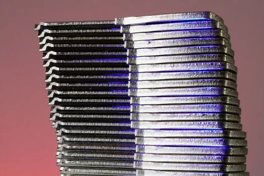
A thin, wide bar can dissipate heat more effectively than a thick, stubby bar having the same cross-sectional area because more surface is exposed to air [S2]. Thickness changes not only resistance but also the available cooling area and current distribution, so the 1.2 A/mm² calculation should not be applied without checking thermal behavior.
One published comparison states that copper busbars of at least 10 mm thickness have 20% higher ampacity than bars of 5 mm thickness or less at the same width because of improved heat dissipation [S6]. This comparison concerns open-air thermal performance and does not establish a universal correction for enclosed switchgear [S6].
Installation details can shift the result substantially. Contact holes should be centered, the full contact face should meet the mating surface, and burrs or ridges created by drilling or stamping should be removed [S4]. Tinning does not materially change DC resistance along the bar length, but it provides corrosion protection and improved compatibility with dissimilar metals [S4].
Use the calculation as the starting point
The preliminary sizing workflow is straightforward: calculate load current, apply a safety factor, select copper width and thickness from the area relation, then verify resistance, temperature rise, mounting and short-circuit withstand.
For example, the copper relationship can be rearranged as required area = calculated current divided by 1.2, giving 83.3 mm² for a preliminary 100 A rating before thermal verification [S1].
Large copper conductors can also be compared with adjacent material families such as alloy steel for mechanical support or secondary conductors, but the electrical busbar selection remains governed by the specific conductor material and joint arrangement.
Verify the installed bar before purchase

Traceable design inputs are more valuable than a single catalog ampacity: record the copper grade, width, thickness, mounting position, ambient temperature, permissible temperature rise, number of parallel bars and applicable project requirement before releasing the busbar schedule. [S1]
The next checks should cover the manufacturer’s dimensional tolerances, surface finish, joint hardware, enclosure ventilation and short-circuit duty. If the calculated value and the thermal result diverge, the lower verified value governs the design.