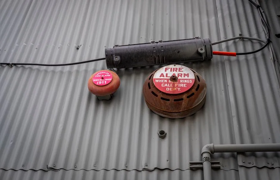
ISO 13850:2015 specifies functional requirements and design principles for machinery emergency stops across electrical, hydraulic, pneumatic, and other energy types [S1][S5].
The emergency-stop function must remain available and operational, be initiated by one deliberate human action, override normal controls, and maintain the safe stop condition until an intentional reset [S4][S9].
Scope and safety-function boundaries
ISO 13850:2015 applies to the emergency-stop function and its actuator, reset arrangements, control span, stop categories, and safety-rated implementation.
The standard is independent of the energy used to control the machine. It therefore applies whether the emergency stop ultimately removes electrical power, commands a hydraulic or pneumatic circuit to stop, or coordinates a combination of machine functions [S1][S2].
For a safety architecture review, the relationship between ISO 13850 and the performance-level requirements is covered in ISO 13849 vs IEC 62061 for Machine Safety.
Actuation, visibility, and operator intent
The operator must be able to identify, see, and quickly reach the control device. Actuation must stop the hazardous process as quickly as possible and must not depend on a sequence of several deliberate actions [S6][S9]. The emergency-stop function must also be available and operational at all times, rather than becoming dependent on an ordinary operating control or operating mode [S4].
Placement is a design decision, not a hardware afterthought. The device should be visible from the operator's working position, accessible without tools or hazardous reach, and positioned so it can be actuated without hesitation. These are functional requirements supported by the standard's design principles and guidance on intended actuation [S1][S4].
Positive operation and device architecture
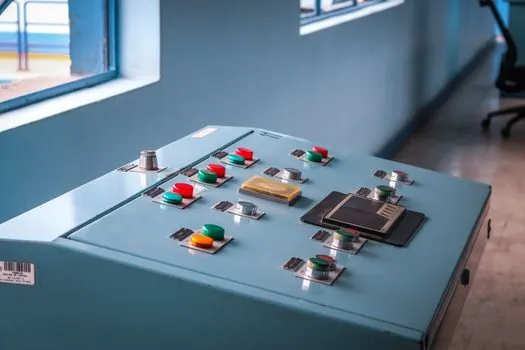
Emergency-stop controls must support positive operation, with actuator movement directly and mechanically driving the contacts rather than relying on a separate sensing element to infer the button position [S7][S8]. A direct-drive arrangement makes the electrical state an outcome of the operator's physical action, reducing dependence on spring position, plunger geometry, or non-contact detection.
The emergency-stop switch must also support latching. After actuation, the emergency-stop function remains in the safe-stop condition until an intentional reset, and the emergency-stop device does not release merely because the actuator is pushed back [S4].
A conventional two-position device can provide this behavior through a positive-opening arrangement, while a twist or pull release is used where the design must make deliberate release easier. The emergency light should be treated separately from actuation and reset, because illuminated indication does not itself establish that the emergency-stop contacts or safety logic have changed state.
Reset methods and deliberate human action
Reset must require deliberate action, and the method must be described in the operating instructions. ISO 13850 guidance identifies automatic reset as an unrecommended arrangement because it can remove the stopped condition before personnel have had the opportunity to address the hazardous condition [S4].
Manual, push-button, pull-cord, or twist-release arrangements are judged by their ability to prevent unintended resetting while allowing an intentional action by an authorized operator. The design should also make the unlatching direction clear where an indicator is provided [S4].
A practical reset sequence is: actuate the emergency stop, allow the hazardous process to reach the required stopped state, investigate and correct the cause, clear or guard the danger zone, and then perform the specified manual release or reset. The release should not restart the machine automatically, and the reset control should not be positioned where a person can operate it accidentally during normal machine use.
Stop categories and performance requirements

ISO 13850:2015 organizes the emergency-stop function by the category of stop and by the safety performance required for the implementation. Category 0 stops the machine by immediate removal of power to the machine actuators; Category 1 performs a controlled stop with power removal afterwards; and Category 2 supplies a controlled stop while power remains available during the stop [S5].
The required category must come from the machine's risk assessment rather than from device marketing.
For selection, an electrical direct-drive device is straightforward to inspect and integrate with a safety relay, while hydraulic or pneumatic systems need a stop circuit matched to their stored-energy behavior. The decision criteria are stopping time, energy isolation, restart prevention, diagnostic coverage, and the required PLr or SIL, not simply the actuator color or contact count.
Comparing emergency-stop implementations
A mechanical, direct-drive emergency-stop switch provides positive contact operation, a visible latched state, and simple local maintenance [S7][S8]. A safety-relay interface can monitor contacts and control removal of hazardous energy, but it adds components and wiring that must be included in the safety calculation and validation.
A pull-cord emergency stop suits long travel equipment such as conveyors because the operator can actuate it from a distance, but it introduces line tension, rope routing, and switch-travel considerations. A foot switch can support a specific workstation, but it is unsuitable where accidental operation, obstructed access, or the absence of the operator's foot would defeat the intended response.
Across these options, direct-drive local control gives the clearest positive mechanism, relay-based control supports broader safety functions, and pull-cord control improves reach on long machines. All three must remain operational, latch, require intentional reset, and achieve the risk-assessed stop category and performance level.
Application limits and common design failures

ISO 13850:2006 was withdrawn on 2015-09-30 and replaced by ISO 13850:2015, so procurement documents should identify the 2015 edition rather than the withdrawn 2006 edition [S3][S5]. ISO 13850:2015 is a Type-B standard for emergency-stop principles, and equipment compliance alone does not establish that the complete machine is safe [S4].
Common failures include placing the device where the operator cannot see or reach it, using an ambiguous reset arrangement, allowing automatic restart, relying on a non-positive control element, or omitting the reset sequence from the manual. Another failure is treating the emergency stop as the only safeguard. The machine still requires its risk assessment, safeguarding, protective measures, and validation to address identified hazards.
The safety interlock switch is a different safety function, normally used for guard or access control. It can support safe operation, but it should not replace the requirement for an emergency stop where a machine falls within the standard's scope.
Verification before machine acceptance
Verification should demonstrate at least one emergency-stop actuation at every operating mode, a hazardous-process stop consistent with the selected category, maintained operation after release of the actuator, and restart only through the defined reset sequence. Testing should cover the 2015 requirements on positive operation, red actuator and yellow background, intended actuation, and prevention of unintended resetting [S4][S5][S8].
The test record should identify the emergency-stop device, its location, the controlled hazard, the energy type, the stop category, the reset method, and the safety architecture. It should also record functional results for normal stop, emergency stop, latch, reset, restart, and control-circuit failure, with acceptance criteria tied to the machine risk assessment rather than only a successful button press.
Procurement and acceptance should close on four trackable items: the ISO 13850:2015 clause matrix, the selected PLr or SIL rationale, a witnessed stop-and-reset test, and an operator instruction covering activation and deliberate reset [S4][S5].