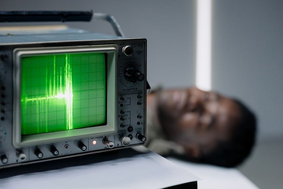
An eddy current tester inspects electrically conductive parts by inducing surface currents and reading impedance changes, making it the default method for surface-breaking and sub-surface defects on tubes, bars, wire, and bolt-holes [S2][S3].
A phased array ultrasonic system uses multi-element probes with computer-controlled pulse timing to steer, focus, and sweep an ultrasonic beam through a test piece, producing sectorial and C-scan images of internal geometry [S7][S8]. The two technologies operate on different physical principles and target different defect populations, which is why spec-driven procurement treats them as complementary rather than interchangeable.
Operating Principle and Penetration Depth
Eddy current testing relies on electromagnetic induction: a coil driven at 64 Hz to 4 MHz on instruments like the EEC-24 induces Foucault currents in a conductive test piece, and flaw-induced impedance changes are read as phase and amplitude shifts [S1]. The standard-depth rule of thumb cited across NDT training material is that ECT is sensitive to the top few millimetres of a conductive surface, with deeper penetration possible at lower test frequencies on non-ferromagnetic materials [S2].
Phased array UT uses longitudinal or shear wave pulses emitted from independently timed elements, typically operating in the 1–10 MHz band; TWI's reference material describes a phased array probe as "a set of ultrasonic testing (UT) probes made up of numerous small elements" whose beam is "focused and electronically swept across an inspection piece" [S7]. PAUT routinely inspects full weld thicknesses in 10–50 mm plate, with depth-sizing capability tied to wedge angle, element count, and focal laws [S7][S8]. The penetration gap is the dominant reason a single ECT or PAUT unit rarely covers a full inspection scope.
Speed, Throughput, and Surface Coupling
Industrial ECT is built for continuous in-line throughput: the EEC-24 specifies a detection rate of 6 m/s (350 m/min) on metal tube, bar, and wire, with adjustable probe excitation of 1–8 V and 0–90 dB gain in 0.5 dB steps [S1]. The technique is non-contact when using a probe gap, requires no couplant, and is therefore compatible with hot or moving product lines [S2][S3].
PAUT requires a couplant layer (gel, water, or shoe) and slower encoded scans, typically tens to hundreds of millimetres per second depending on the encoder pitch and coverage requirement. TWI notes that PAUT is widely deployed in welds, corrosion mapping, and complex geometries, and is "an advanced non-destructive inspection technique" relative to manual UT [S7]. For high-volume surface inspection of conductive stock, ECT throughput exceeds PAUT by 1–2 orders of magnitude, but PAUT delivers volumetric data ECT cannot.
Defect Types and Detection Limits
ECT detects surface and near-surface defects including surface cracks, axial cracks (un-puddle-weld, submerged joint, open crack), pucker, scar-over, impression, nick, and absciss layer on conductive metal tube [S1]. Eddy current array (ECA) extends coverage by electronically multiplexing multiple coils in one probe assembly, generating C-scan images of an area in a single pass [S3].
PAUT detects and sizes volumetric flaws such as slag, porosity, lack of fusion, and sidewall cracks in welds, plus laminations and inclusions in plate and forging [S7][S8]. For weld procedure qualification under ISO 9712 / ASME and similar codes, PAUT or TOFD is typically the method prescribed because depth and through-thickness location must be reported — data that ECT cannot resolve at typical test-piece thicknesses.
Probe Format, Calibration, and Standards
ECT hardware centres on a single or array probe plus an impedance-plane instrument; the EEC-24 lists 1 channel, 64 Hz–4 MHz, 0.1–10 gain ratio, and 0–360° phase rotation at 1° resolution [S1]. Eddy current array probes package multiple coils side-by-side; Olympus' tutorial states each coil "produces a signal relative to the phase and amplitude of the structure below it," with data referenced to encoded position and time for C-scan imaging [S3].
PAUT hardware centres on a multi-element probe (commonly 16, 32, 64, or 128 elements), a wedge matched to the test material, an encoder, and an instrument with focal-law calculator. Calibration requires reference blocks with side-drilled holes or notches to set sensitivity, time-corrected gain, and wedge delay per the applicable code (e.g., ASME V Article 4, ISO 13588). The complexity gap means PAUT operator certification is more demanding, and total cost of ownership — instrument, probe, scanner, software — is materially higher than a single-channel ECT bench.
Decision Matrix: ECT vs PAUT by Use Case
On a criteria-based comparison, ECT and PAUT separate cleanly:
- Inspection of tubes, bars, wire for surface cracks at line speed (up to 6 m/s): ECT, ECA preferred [S1][S3].
- Code-compliant weld inspection requiring depth sizing in ≥6 mm plate: PAUT, often paired with TOFD for full-volume coverage [S7][S8].
- Heat-exchanger and boiler tube inspection (near-surface, ID/OD): ECT bobbin or remote-field probes for high throughput; PAUT for localised pitting depth where access allows [S2].
- Aerospace wheel, bolt-hole, and surface fatigue inspection: ECT array for fast C-scan coverage of large curved surfaces [S3].
For mixed-scope projects, procurement typically spec's both: PAUT for welds, ECT/ECA for tubes, bars, and surface-breaking flaws, with the instrument data exported into a shared NDT software platform for traceability.
Limitations and Failure Modes
ECT is blind to non-conductive coatings, deep sub-surface flaws in ferromagnetic materials, and any defect deeper than the skin depth at the chosen test frequency. Micro-Epsilon's product literature on eddy-NCDT sensors notes the technique is also highly sensitive to "ferromagnetic materials and electrically conductive materials" and to "external electromagnetic fields," which can drive noise on shop floors without proper shielding [S4]. On magnetic materials, magnetic flux leakage or magnetic particle inspection is usually substituted, or saturation probes are required.
PAUT cannot inspect without a couplant path, struggles on very rough or heavily corroded surfaces, and the data set is only as good as the encoded scan — missed encoder pulses produce misregistered C-scans. Coupling loss in field conditions is the single most common root cause of PAUT sensitivity loss, addressed by water-column scanners, soft shoes, and encoded manual scanners [S7][S8].
Selection Guidance and Market Signals
Specify ECT when the scope is conductive material, surface or near-surface, high throughput, no couplant tolerated, and operator skill is mixed. The EEC-24 example demonstrates the typical industrial ECT instrument envelope: 20 kg, 490×426×177 mm, AC 220 V, single channel, 64 Hz–4 MHz, 6 m/s throughput [S1]. Specify PAUT when the scope is weld qualification, depth sizing, thick-section forging, or any code that names phased array in the procedure [S7][S8].
Market and product signals to track: ECA probe density and channel count for tube/wheel inspection, growing use of ECA for train wheel inspection where analysts must detect "even minute flaws" rapidly over large curved areas [S5]; and PAUT phased-array firmware releases that add 64/128-element focal laws and TOFD dual-mode operation [S7]. For plants standardising on a single platform, integrating an ECT channel for tubes and bars alongside a phased array ultrasonic system for welds is the most defensible route, with both streams exported to a common NDT database. Adjacent spec work — for example, ultrasonic sensor selection for distance/level feedback — follows a similar trade-off logic on frequency, housing, and output, and is worth aligning to the same NDT instrument vendor where possible.
Component reference pages worth checking: ultrasonic flowmeter.