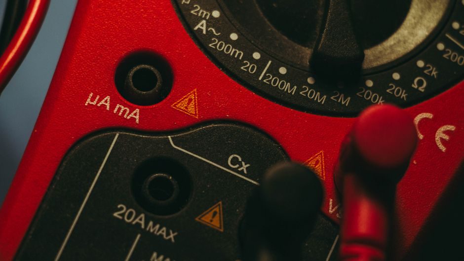
Selection of an eddy current tester starts with four numbers: usable frequency span, gain range and step, maximum inspection speed, and probe family supported. Misreading any of these turns a five-figure instrument into a paperweight on day one.
Eddy current testing (ECT) is an electromagnetic induction NDT method: a coil excited at 100 Hz to several MHz drives Foucault currents in a conductive part, and defect-, conductivity-, or geometry-induced changes in coil impedance are mapped on an impedance plane or strip-chart [S4][S5]. Modern digital ECTs add phase-rotation control, digital filtering, and automatic defect counting, but the underlying physics — penetration depth falls as frequency and conductivity rise — is unchanged.
Frequency Range and Penetration Depth: The First Gate
Frequency span directly sets the depth of inspection: higher test frequencies (1–5 MHz) resolve tight surface cracks; lower frequencies (≤500 kHz) reach sub-surface flaws in non-ferrous parts [S4]. Production ECTs such as the EDDYSUN EEC-24 specify 64 Hz to 4 MHz with 1 V to 8 V adjustable probe excitation, a span broad enough to swap probes between surface-crack and sub-surface modes without retuning the instrument [S2].
Portable ECTs compress the range to keep size and power down: the SMART-301 covers 100 Hz to 5.5 MHz in a 180×115×40 mm, 650 g housing, which is enough for most field weld and tube audits but not for low-frequency sub-surface scans [S3]. Buyers should match the published low-end frequency to the deepest defect class on the drawing — 64 Hz or 100 Hz minimums are typical, and a unit starting at 1 kHz will miss lift-off-tolerant sub-surface work.
Gain, Phase, and Filtering: Resolution vs Noise
Gain range and step size determine the smallest impedance change the instrument can resolve. The EEC-24 industrial unit offers 0 to 90 dB gain in 0.5 dB steps with 0–360° phase rotation at 1° precision, and adds high-pass and low-pass digital filters to suppress drift [S2]. The SMART-301 portable offers 0 to 48 dB in 0.5 dB steps with the same phase-rotation resolution, plus 1 Hz to 100 Hz digital-filter bandwidth — adequate for crack detection on copper and steel tube, but short of the headroom needed for sub-millimetre conductivity sorting [S3].
Phase rotation accuracy is a quiet selection criterion: 1° phase resolution is now the floor on digital ECTs, and it directly controls defect-class separation on the impedance plane (e.g. distinguishing a drill hole from a natural crack) [S2][S3]. If the datasheet does not state a phase-rotation figure, treat the unit as legacy analogue and move on.
Throughput and Form Factor: Bench, Inline, or Portable

Inline bench ECTs are designed for moving product: the EEC-24 specifies a 6 m/s (350 m/min) detection rate at 20 kg and 490×426×177 mm, sized for fixed mounting over a tube, bar, or wire line [S2]. At 20 kg and AC 220 V mains, it is not a field instrument — it is a station that the line feeds.
Portable ECTs trade throughput for mobility. The SMART-301 runs 8+ hours on a 7.4 V / 3500 mAh lithium pack, accepts DC 8.5–12 V external power, and weighs 650 g — small enough to clip onto a harness or carry into a weld cell [S3]. Field users accept a lower gain ceiling (48 dB vs 90 dB) and a narrower frequency floor (100 Hz vs 64 Hz) in exchange for that form factor. For most plant-floor use cases the choice is binary: fixed line or hand-held, not a single instrument doing both.
Probe Compatibility and Defect Class Coverage
Probe support is decided by the application: absolute probes for simple geometry and conductivity, differential probes for crack detection on moving tube, and reflection (send-receive) probes for bore and fastener inspection [S3]. A spec line that lists only "standard probe" is a red flag — qualified ECTs publish the supported probe family and the matching test frequencies.
Defect class coverage should be matched to the supplier's stated use cases, not extrapolated. The EEC-24 datasheet explicitly covers surface cracks, axial cracks (un-puddle-weld, submerged joint, open crack), pucker and scar over of seamless pipe, and impressions, nicks, and absciss layers [S2]. The SMART-301 lists surface cracks on copper tube, pinchers on seamless steel tube, steel pit, guide-board nicks, transversal cracks, and separation layers [S3]. If a defect type is not on the sheet, treat the unit as unvalidated for that class — even if the frequency span suggests it should work.
Data Output, Storage, and Integration
Data-handling specs decide whether an ECT can drop into a real production line. Industrial ECTs need mass storage of test programs, strip-charts, and defect logs, plus an external alarm output the line PLC can read; the EEC-24 publishes real-time and time-delayed alarm outputs with internal/external clock synchronization, plus multi-language UI (English, Simplified Chinese, Traditional Chinese) [S2]. Portable units typically expose USB for post-test download and PC-side impedance-plane rendering, as the SMART-301 does [S3].
Buyers should confirm three integration points before purchase: (1) alarm output type — relay, open-collector, or PLC-level bus; (2) data file format for QA traceability (binary strip-chart plus CSV defect log is the realistic floor); (3) whether the unit supports automatic defect counting, length measurement, and end-tail signal excision, all standard on industrial ECTs but not always present on portable units [S2][S3].
When ECT Is the Wrong Tool
For ferromagnetic heavy-wall pressure-vessel inspection, ultrasonic testing typically penetrates where ECT cannot, and for volumetric flaw sizing in welds, radiography remains the baseline [S4][S5]. Specifying ECT where the substrate is non-conductive, or where the target flaw is deep and oriented unfavourably to the induced current path, produces false confidence rather than data.
ECT is also a poor fit for coating-only thickness work on non-magnetic substrates when the underlying part is non-conductive; instruments purpose-built for that job, such as a coating thickness gauge-class eddy or magnetic device, are usually a better buy than a general-purpose ECT. For broader NDT method selection, the industrial X-ray vs coating thickness gauge decision map is a useful cross-reference.
Selection Shortlist Logic
A practical shortlist starts with three filters. Filter 1 — frequency span: must cover the lowest and highest test frequency the defect mix requires (e.g. 64 Hz to 4 MHz for mixed surface and sub-surface work; 100 Hz to 5.5 MHz for field tube inspection). Filter 2 — gain headroom and step: 0–90 dB / 0.5 dB step for inline crack sorting; 0–48 dB / 0.5 dB step is acceptable for portable surface work. Filter 3 — form factor and integration: 20 kg bench unit with mains power and PLC alarm output for a fixed line, or sub-1 kg battery unit with USB download for in-plant audits [S2][S3].
Procurement should also confirm probe vendor support, datasheet-listed defect class coverage, and the published phase-rotation precision (1° is the current floor). If any of these are absent, the unit is unqualified for production NDT regardless of price, and the choice should be deferred to a documented comparison set — the same gate logic used when selecting a hardness tester or a deadweight tester. For thicker ferrous components where ECT falls off, ultrasonic and eddy-current method cross-comparisons and roundness-gauging workflows (roundness tester) usually appear in the same QA specification stack.
Trackable signals for the next 6 months: published updates to the EEC-24 and SMART-301 firmware revision notes, any new probe family releases from EDDYSUN and Criterion NDT, and any cross-vendor standardization of impedance-plane file formats for QA traceability.