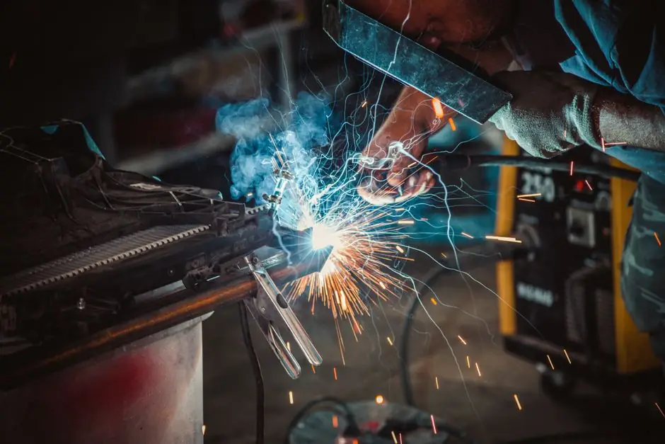
The latest version of electroslag welding, ESW-NG, uses a narrow gap of about ¾ inch.
The process is a single-pass method for thick materials in vertical or near-vertical positions, and its real production rate depends on deposition speed plus positioning, fixture loading, slag handling, cooling, and inspection.
What determines electroslag welding cycle time?
The productive weld interval is calculated from the deposited cross-sectional area and the deposition rate, while the complete production cycle adds handling and positioning around the deposited weld [S4]. For an electroslag pressure welder, the calculation should distinguish arc or slag time from the time required to establish a sound molten pool and complete the joint.
ESW-NG uses a narrow gap of about ¾ inch, while electroslag welding is generally a single-pass process used in a vertical or near-vertical position. The cycle also depends on the welded length, joint thickness, wire-feed rate, slag-pool depth, and the arrangement of the containment shoes or plates.
Cycle time is not simply the duration of the welding current. A practical production estimate should include:
1. Joint preparation and fit-up before the process starts.<br>2. Initial arc start and establishment of the conductive molten slag pool.<br>3. Travel time for the single-pass deposit.<br>4. Run-off, slag removal, and cooling or handling between welds.<br>5. Positioning, fixture loading, inspection, and rework time.
The cited factory model treats a weld cycle as actual weld time plus positioning time plus fixture load time, and notes that each element can be significant depending on the project [S4]. That definition is more useful for production-rate calculations than quoting the deposition rate alone.
Deposition rate versus usable production rate
Production of a sound ESW-NG weld requires about one inch of molten slag floating atop a molten weld pool. The process uses resistance heating after the initial arc is extinguished, so the production speed depends on maintaining a stable slag pool, controlled heat transfer, and continuous wire delivery.
A direct comparison of the main welding approaches shows why deposition rate cannot be treated as shop output:
For cycle-time control, compare alternatives using at least four criteria: deposited metal per hour, travel speed, position restrictions, and non-weld time per joint [S1][S4][S5]. A process with a lower deposition rate can still produce more parts per shift if setup is easier and repositioning is shorter, while a high-deposition process can lose its advantage when run-off, cooling, or inspection dominates.
How to calculate a production-rate estimate
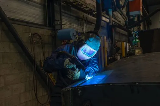
The core weld-travel calculation is weld length divided by qualified travel speed. This is a planning figure, not a substitute for a qualified production trial, because section geometry and machine settings can change the effective rate.
A second route uses mass deposition. If the required weld-metal mass is M kilograms and the qualified deposition rate is D kilograms per hour, the theoretical deposition time is M divided by D. The shop must then add a measured allowance for positioning and fixture loading, consistent with the definition of weld cycle time in the manufacturing method [S4].
The general cycle model is:
<strong>Total cycle = joint preparation + arc start and pool establishment + weld travel + run-off and slag removal + repositioning + fixture loading + cooling or handling + inspection and rework.</strong>
For production planning, separate two outputs. Gross cycle time is the elapsed time for one complete joint. Standard output rate is good joints per hour after accounting for rejects and rework. A department can achieve good deposition speed but still miss its production target if wire feeding, shoe placement, slag removal, or inspection creates recurring delays.
Track at least 5 values for every production run: joint length, actual weld time, positioning time, fixture load time, and inspection or rework time. The supplied manufacturing method identifies actual weld time, positioning time, and fixture load time as the principal cycle components, while the National Board identifies deposited weld metal per hour as a cost measure [S4][S5].
Where electroslag welding fits, and where it does not
ESW is intended for thick materials in vertical or near-vertical positions, and ESW-NG specifically uses a gap of about ¾ inch [S1][S3]. This makes it relevant to heavy industrial joints, pressure-vessel fabrication, bridge structures, and other applications where a single-pass deposit can replace multiple arc-welding passes.
The process is not the right choice for thin material. TWI also identifies positioning and cooling as constraints, because ESW operates in a vertical or near-vertical orientation and develops high temperatures that can require additional cooling arrangements [S3]. Its coarse grain structure can reduce toughness, so impact performance must be qualified for the governing material and product requirements.
The process is also unsuited to a production cell built around small components with short welds. In that case, a 1 inch per minute deposition rate may be offset by repeated fit-up, handling, and positioning. An arc welder with a procedure qualified for the actual joint may deliver better total output when the weld volume is small and handling dominates.
Vertical and near-vertical access, thick sections, and a need for high deposition rates favor ESW. Thin sections, frequent reorientation, short welds, or applications unable to accommodate the required containment and cooling arrangements do not.
Process controls that protect the cycle
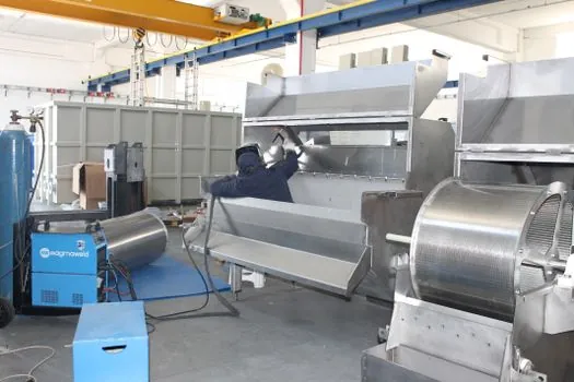
A sound ESW-NG weld requires about 1 inch of molten slag above the weld pool, together with a motorized flux dispenser, wire feeder, water circulator, and welding power supply [S1]. These are not optional process accessories. If slag depth or wire delivery becomes unstable, the joint can lose time through interruption, inspection, or repair.
Containment is provided by a sump, run-off tabs, water-cooled copper welding shoes or metal containment plates, and sealant [S1]. The shoes must be detailed for the heat-transfer requirement and joint orientation, because poor heat management can affect both metallurgical quality and the time needed to complete or release the weld.
Constant-potential DC or square-wave AC power supplies are suitable for ESW-NG [S1]. Narrow-gap ESW has been accepted by AASHTO for common bridge steels under AWS D1.5, and it also satisfies AISC-defined demand-critical weld criteria [S1]. Those qualifications do not replace project-specific welding procedure qualification or acceptance requirements.
Slag inclusion and porosity are described as atypical for ESW-NG, but this does not make inspection optional [S1]. The broader disadvantage of ESW includes coarse grain structure and possible toughness reduction, so thermal-cycle and mechanical-property requirements remain central to the production plan [S3].
Production evidence from pressure-vessel fabrication
A technical study of electroslag welding for nuclear-reactor pressure vessels examined longitudinal and circumferential joints, thermal-cycle effects, filler materials, welding equipment, heat treatment, and nondestructive-testing requirements [S2]. Its production rationale was direct: larger pressure vessels created pressure on production rates and delivery times, and automatic electroslag welding offered a route to time savings.
The study also distinguishes electroslag welding from electroslag remelting, covering applications in reactor vessels, chemical equipment, refineries, and power equipment [S2]. That breadth matters because cycle time is tied to fabrication architecture. Circumferential vessel welds, longitudinal seams, and structural bridge joints have different positioning, containment, access, and inspection burdens, so one plant-level output factor cannot be transferred automatically between them.
For a production-rate decision, the strongest evidence is the qualified joint on the actual product. Measure actual cycle data by joint geometry and thickness, then separate weld travel from handling and inspection. The related electroslag welder transformer sizing for bar size discussion addresses a different constraint, namely power-source sizing, but the same principle applies: equipment must be matched to the qualified process rather than selected from deposition speed alone.
What production metrics to track
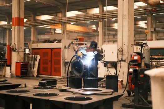
Track nominal deposition rate and actual joint output separately. The published ESW-NG reference provides approximately 1 inch per minute and a ¾ inch narrow gap, while the National Board cost framework measures welding productivity in pounds of deposited weld metal per hour [S1][S5]. Together, these support two operational views: speed along the joint and mass delivered per labor hour.
At the machine level, record weld travel time, wire interruptions, slag-pool adjustments, run-off handling, and equipment setup. At the cell level, record fixture loading, repositioning, cooling, slag removal, inspection, and rejection. The manufacturing reference notes that actual weld time can be a small fraction of total arc time on a large tubular structure, which makes non-weld time a decisive production variable [S4].
Use two release gates before claiming a production rate. First, demonstrate stable deposition over the qualified joint range, including the expected thickness and length variation. Second, repeat the cycle with normal positioning, inspection, and rework steps included. A 1 inch per minute deposition result alone is a process capability figure, not a defensible shift-output promise.
For the next planning revision, capture actual cycle times for at least 3 representative joint lengths and calculate good joints per hour from complete elapsed time. This establishes a shop-specific factor for handling and inspection instead of relying on a generic deposit-rate multiplier.