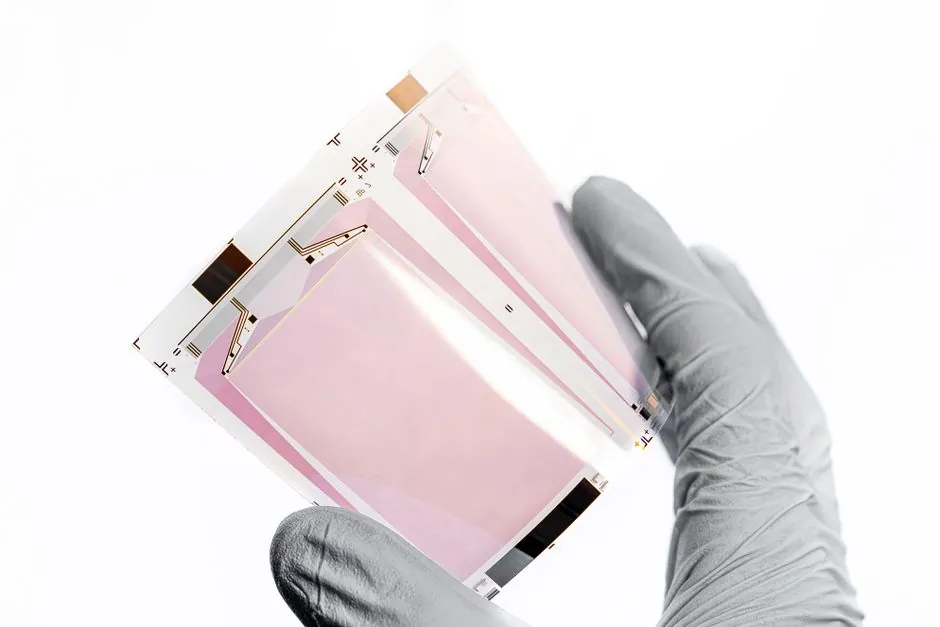
Semiconductor strain gauges produce an output signal approximately 75x greater than a foil strain gauge for the same applied strain, according to Humanetics' published guidance on silicon sensing elements [S6]. That headline figure is the central reason engineers debate the two technologies whenever a load cell, force sensor, or weighing system moves from prototype to production.
The choice is not just a sensitivity number. It is a trade between gauge factor (GF), linearity error, temperature coefficient of resistance (TCR), fatigue life, gauge area, and the cost of the signal conditioning that follows. The matrix below lays out what the published 2020-2025 literature actually supports, with the [S#] sources cited inline.
Sensitivity and Gauge Factor: Where the Two Technologies Actually Sit
Metal foil strain gauges based on constantan or Karma alloys typically run a gauge factor near 2.0, while doped-silicon semiconductor gauges sit in the 100-175 range, giving the 50-75x output advantage widely cited for silicon sensors [S6][S4]. The same silicon element that boosts signal also creates a non-linear resistance-to-strain curve that drifts 10-20% from a straight-line equation without software compensation [S4].
For a strain gauge bonded to a 350 ohm foil element, microstrain resolution is usually limited by the Wheatstone bridge excitation noise floor rather than the gauge itself. For a 1000 ohm diffused-silicon element, the same excitation delivers a signal large enough to resolve single-digit microstrain in laboratory-grade load cells, which is why precision balances and high-sensitivity force gauge instrumentation lean toward semiconductors.
Linearity, Temperature Drift, and Creep: The Real-World Cost of That 75x
Foil gauges hold their resistance-to-strain relationship close to linear across the typical operating range, with predictable creep governed by the carrier backing and adhesive chemistry. Semiconductor gauges exhibit greater sensitivity to temperature variations and a higher tendency to drift compared with metallic foil sensors, and their non-linearity runs 10-20% off the ideal straight line unless corrected in software [S4][S9].
Creep error in resistance strain force sensors is driven by sustained load, temperature swing, adhesive shear, and grid-wire end effects; these are the dominant error sources for both gauge families, and they are why metrology standards work hard on compensation algorithms [S1]. In practice, a foil gauge on a properly heat-treated sensing beam reaches its steady creep behaviour in 1-2 weeks, while semiconductor load cells require more aggressive temperature compensation and periodic re-zero, especially when used as a pressure gauge element in a hydraulic test rig.
Size, Overload Margin, and Mechanical Robustness
Semiconductor gauges win on footprint: a diffused-silicon element is much smaller and the production cost per element is much lower than for a metallic foil sensor, which makes them the default for miniature and high-channel-count layouts [S4]. Foil gauges still dominate wherever the sensing element must survive mechanical abuse, weld heat, or long-term outdoor exposure, because the polyimide-backed metal grid tolerates abuse that cracks a brittle silicon die [S3].
Because semiconductor strain gauges are more sensitive to slight changes in tension, they require less strain to produce a usable signal, which improves overload margin at the system level; a smaller strain input means the host structure stays in its elastic range further into an overload event [S5]. The trade is that once you exceed the silicon die's strain limit, the element fails abruptly rather than gradually, so a semiconductor load cell usually needs a mechanical stop to absorb the over-range energy that a foil gauge would simply shrug off.
Decision Matrix: Foil vs Semiconductor Across Four Criteria
Sensitivity: semiconductor wins decisively, roughly 50-75x the gauge factor of constantan foil and a usable output from microstrain inputs [S6]. Linearity and temperature behaviour: foil wins, holding close to a straight line with predictable TCR, while silicon needs software correction for the 10-20% non-linearity and its higher temperature sensitivity [S4][S9]. Mechanical robustness and fatigue life: foil wins, with long-proven performance in harsh, outdoor, and high-cycle installations [S3]. Cost per channel and miniaturisation: semiconductor wins, with smaller die area and lower per-element cost once volume is in the thousands [S4].
For a process-engineer shortcut: pick foil for field-installed weighing, structural health monitoring, and any height gauge or weighing platform that must hold calibration across seasonal swings; pick semiconductor for laboratory force gauge heads, low-deflection transducers, and embedded OEM sensing where the host electronics can carry the temperature compensation burden.
Use Cases That Lock the Choice In
Web tension control on film, paper, and foil converting lines is the classic semiconductor territory, where DFE and similar OEMs have shipped silicon-element load cells since 1984 for resolution, longevity, and low-noise output [S2]. Structural monitoring of bridges, cranes, and pressure vessels stays in the foil camp, where the gauge has to survive decades of thermal cycling and the literature documents the metrology standards for that long service life [S1].
Medical and dental force sensing, crash-test dummy instrumentation, and small-parcel weighing all benefit from the 75x signal advantage, since the host electronics can be compact and battery-powered [S6]. Where the gauge is embedded in a high-vibration casting or a thickness gauge head scraping across a moving web, foil's mechanical tolerance still pays for itself even at the cost of a heavier signal-conditioning chain.
Limits, Failure Modes, and What the Spec Sheet Will Not Tell You
Two failure modes catch engineers out. First, semiconductor gauges drift with temperature at a rate that foil gauges do not, so a sensor that works on the lab bench can lose 5-10% full scale across a 50 K swing in a plant [S4][S9]. Second, creep and zero shift in a load cell are more often caused by transducer preloading, stress relief of the sensing beam, and adhesive final cure than by the gauge element itself, so swapping a silicon element for a foil element rarely fixes an unstable reading without addressing installation and beam metallurgy [S2].
The other hard limit is non-linearity: the resistance-to-strain relationship in silicon varies 10-20% from a straight line, which forces software compensation in the indicator or transmitter, and that compensation only holds if the calibration temperature tracks the operating temperature [S4]. For standards-driven work, a foil gauge on a heat-treated beam still gives the most traceable, most repeatable result per unit cost.
Sourcing, Standards, and Trackable Signals
Verified published comparisons of the two technologies cluster in the 2019-2025 window, with PatSnap's 2025 fundamentals piece [S3] and the 2020 PMC review of resistance strain force sensors [S1] the two anchor references; vendor-side guidance from DFE [S2], Montalvo [S5], and Humanetics [S6] carries the application-side detail. The 1970 introduction of silicon semiconductor strain gauges for automotive use is the baseline date for any technology-comparison claim about the silicon side [S4].
The 2020 review of resistance strain force sensors discusses work toward a metrology standard for such sensors and reviews the current status of wide-bandgap semiconductor (SiC, GaN) strain sensors [S1]. For procurement, expect silicon-element load cells to keep winning new OEM designs below 50 kg full scale, and foil-gauge platforms to retain the structural-monitoring and heavy-capacity force gauge markets where linearity and fatigue life still set the spec.
For related coverage, see OEE in Continuous Process Industries: Yes, With Specific Adaptations.