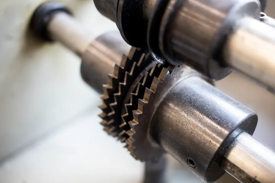
A gasket is a static compression element placed between two flat mating surfaces and tightened to a defined bolt load, while a mechanical seal is a dynamic interface of lapped faces that separates a rotating or reciprocating shaft from a stationary housing under controlled face pressure and a thin fluid film.
Mixing them up costs plants money: a gasket forced into a pump stuffing box leaks within hours, and a mechanical seal bolted across a flange face cannot follow shaft runout. The 2026 sealing market continues to push engineers toward clearly separating static and dynamic duty before material selection [S1][S2].
Where the Two Technologies Actually Live on a P&ID
Static duty belongs to gaskets. Typical call-outs are pipe flanges, heat-exchanger channel and bonnet covers, manways, access hatches, pump and compressor casing joints, and any other bolted pair that does not move in service [S1][S2]. Compressible sheet, spiral-wound, ring-joint, kammprofile, and PTFE-jacketed constructions are the common choices, selected against pressure, temperature, and media compatibility [S1].
Dynamic duty belongs to mechanical seals. They appear on centrifugal and positive-displacement pump shafts, agitator and mixer shafts, compressor shafts, and any rotating equipment that handles a process fluid that cannot be allowed to track along the shaft [S2][S3]. A bellows seal is one common subtype, used when the process fluid would attack a conventional packed gland or when the secondary sealing path must be metallic rather than elastomeric. Both categories eventually touch a mechanical seal reference, but the engineering logic is inverted: gaskets are sized to bolt load, mechanical seals are sized to balance face pressure, flush flow, and heat rejection.
Decision Matrix: Cost, Pressure, Temperature, Lifetime, Maintenance
Side-by-side on the criteria that drive a real spec sheet, the two technologies trade off sharply. A compressed-fibre or graphite gasket is the lowest-cost static option and tolerates wide chemical families, but it cannot handle a moving shaft, and its leak rate depends entirely on the bolt load, surface finish (typically Ra 3.2-6.3 micrometres for soft cut gaskets), and gasket stress at assembly [S1][S2].
Mechanical seals carry a 5 to 20 times higher unit cost than an equivalent flange gasket, but they extend mean time between repair on rotating equipment from months to years by replacing the uncontrolled stuffing-box leak with a controlled face leak below API 682 or plant-defined emission limits, and they support flush plans (API Plan 11, 13, 32, 53) that a gasket simply cannot deliver [S3][S6]. On pressure, soft gaskets cap out around PN 40 class with full confinement; spiral-wound and ring-joint gaskets push that to ASME Class 600 and above, while balanced mechanical seals routinely cover full vacuum up to about 40 bar on water duty, with cartridge arrangements extending that envelope for hydrocarbons [S1][S3]. On temperature, graphite and mica-filled gaskets reach roughly 600 degrees C in oxidising service, whereas silicon-carbide-faced mechanical seals can run in hydrocarbon service above 200 degrees C with the right elastomer or metal secondary seals [S1][S2].
Materials, Standards, and Failure Modes That Decide the Spec
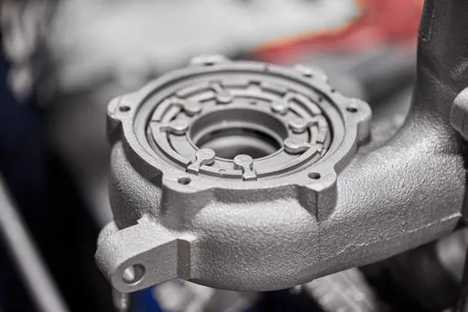
Gasket material choice is media-driven. PTFE and EPDM give broad chemical resistance for acids, caustics, and water; graphite and exfoliated mica carry high-temperature hydrocarbon and steam service; spiral-wound gaskets combine a metal winding (typically 316L stainless) with a non-metallic filler (graphite, PTFE, mica) for cyclic pressure and temperature where a homogeneous sheet would creep or blow out [S1]. Kammprofile (camprofile) gaskets pair a grooved metal core with a soft sealing layer and offer high recovery on thermal cycling, making them common on heat-exchanger flanges [S2].
Mechanical seal material choice is tribology-driven. The two lapped faces are almost always a hard-against-hard pairing: silicon carbide versus silicon carbide for abrasive slurries, silicon carbide versus carbon for water and light hydrocarbons, tungsten carbide versus carbon for upstream oil and gas, and resin-impregnated carbon versus metal for dry-running or low-duty cases [S3]. Elastomers (FKM, EPDM, FFKM, PTFE) are picked for secondary sealing and O-rings against the same chemical compatibility logic as a gasket, with FFKM reserved for the aggressive chemicals and temperatures that would attack FKM [S1][S3]. Standardisation efforts in 2026 are pushing for fewer face materials, fewer elastomer choices, and common cartridge footprints so that inventory and total cost of ownership fall without compromising API 682 duty envelopes [S6].
Installation Discipline: Why Both Are Sensitive to Human Factors
Gasket installation failures are overwhelmingly alignment, torque, and reuse errors: dry-fitting, uneven bolt cross-pattern torque, dirty flange faces, and re-using a compressed gasket are the four most common root causes of static-joint leaks [S1]. Spiral-wound and ring-joint gaskets are single-use; soft cut gaskets sometimes get re-used on a service line, but only if the recovered thickness and surface condition still meet the design gasket stress.
Mechanical seal installation failures are overwhelmingly setting length, sleeve, and lubrication errors. Cartridge seals ship pre-set on a defined setting length between the gland and the shaft shoulder, with slotted bolt holes and flat gaskets that allow the cartridge to register axially before the gland is fully torqued, which removes a large share of the field-error modes that plagued component seals [S3]. Shaft sleeve condition, axial float of the shaft, and the cleanliness of the flush connection decide whether a correctly specified seal survives its first 1,000 hours [S5].
Use Cases and Limits: A Straight Spec Route
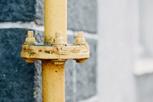
Pick a gasket when the joint is static, the surface finish and bolt load can be controlled, the duty temperature and pressure fit a published gasket stress curve, and the leak rate required is consistent with a bolted joint rather than a controlled face seal. A broad 2026 sealing-skuset covers soft cut, spiral-wound, ring-joint, kammprofile, and PTFE-jacketed constructions in stock [S4], and a spec-first approach to flange finish, gasket stress, and bolt torque remains the most cost-effective route for static service. A practical reference, including material and flange class logic, is laid out in a Gasket Selection Criteria field guide and an O-ring selection criteria guide when the joint geometry narrows to a groove.
Pick a mechanical seal when a shaft passes through a wetted or pressurised chamber, the leak rate must be controlled (typical target: less than 50 ppm VOC for refined hydrocarbons), the process fluid is toxic, hot, abrasive, or valuable, and the maintenance team is set up for cartridge replacement on a defined interval [S3][S6]. A seal is the wrong tool for a static flange regardless of how much the maintenance team would prefer one inventory SKU. A bellows seal is the right mechanical seal subtype when shaft runout is high, when the secondary seal must survive temperature beyond elastomer limits, or when the process attacks the conventional O-ring secondary path. For adjacent rotating-equipment decisions on housings and inserts, the same spec-first logic appears in a pillow block bearing selection guide.
Trackable signals for the next quarter: OEM releases of standardised cartridge footprints that consolidate FKM, EPDM, and FFKM secondary seal options into fewer SKUs, and plant-level moves from component seals to pre-set cartridges for ANSI process pumps to cut installation-induced failures. Both directions reinforce the rule that the first decision is static-versus-dynamic, not material-versus-material.