
A helical gear reducer is only as reliable as the way it is mounted: rigid foundation, laser-aligned shafts, correct fastener grade, oil filled to the right level, and a controlled run-in before the driven load is applied.
Industrial units in current catalogues span 0.18-160 kW rated power, 6-1154 rpm output speed, 20-18000 Nm output torque, and ratios from 1.3:1 up to 249.16:1 [S7]. Parallel-shaft cement-mill drives push past 10 kNm at 48:1 ratio, weighing 80,000 kg with 100,000-hour-rated roller bearings [S2]. Precision planetary helical units carry 0.02-0.12 deg backlash and 2000-10000 rpm input speed [S1]. On the shaft-mounted end, 5:1 to 220:1 ratios and 0.2-220 kW coverage dominate conveyor and mixer applications [S3].
Foundation and Baseplate: Stop the Box From Walking
A helical reducer transmits torque through a gear mesh, and any baseplate flex is converted into angular misalignment that kills bearing life. The reducer must sit on a continuous concrete foundation or a fabricated steel bedplate with a flatness of 0.1 mm per meter and a roughness machined or ground smooth [S5].
Anchor bolts are grade 8.8 or higher for standard units; high-torque cement-mill housings use preloaded anchor systems sized for the full reversing load case. Shim stacks are placed near each anchor point, not under the housing feet centerline, so the foot face stays flat against the bedplate. After the first torque-up, a feeler gauge check under each foot must show no gap greater than 0.05 mm; any gap means a re-shim, not grout poured under load.
Grouting with epoxy or non-shrink cement is done before the input coupling alignment, never after. Vibration-isolating pads are only used for fans and light-duty conveyors, never on heavy mill drives where elastic mounting multiplies mesh loads.
Shaft Alignment: The 0.05 mm Rule and Soft-Foot Control
Coupling alignment between motor and reducer, and between reducer and driven machine, must hold 0.05 mm or better on both offset and angularity for general-purpose units; precision servo-class helical reducers require 0.02 mm [S1]. A dial indicator or laser alignment tool is mandatory - straight-edge methods are not acceptable above 1.5 kW.
Soft-foot checks come first: with four anchor bolts snugged, verify each foot carries load by rotating the coupling and watching for lift. The classic four-foot test reveals a high foot before the laser is even set up. A high foot shimmed to less than 0.05 mm indicator movement corrects the single biggest source of vibration in field installs. Once soft-foot is clean, proceed to angular and parallel alignment.
For shaft-mounted reducers like the HSM, the keyless Taper-Grip bushing eliminates the traditional key seat on the driven shaft and lets the reducer slide axially for belt or chain tensioning [S3]. The driven shaft must still be parallel to the reducer centerline within 1 deg, or the internal gears will side-load.
Fastener Torque and Backstop Integration
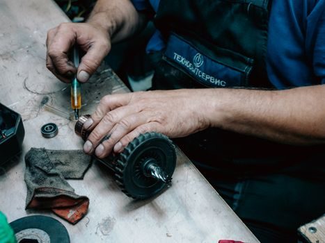
Housing bolts and end-cap bolts follow the OEM torque table, typically tightened in a star pattern to 70 percent first, then 100 percent. Over-torque distorts the housing bore and changes the gear mesh pattern; under-torque allows the case to walk and the oil seal to leak. [S1]
Backstop integration is critical for inclined conveyors, bucket elevators, and mixers where reverse rotation is a safety hazard. The Hansen HSM offers an integrated backstop option, factory-fitted inside the housing, so the installer simply confirms the arrow on the case matches the driven direction [S3]. Field retrofits of a backstop are not recommended on helical units because the input shaft geometry is not designed for the additional thrust load.
For shaft-mount units with optional Taper-Grip bushings, mounting torque is set by the bushing size - typically 30-150 Nm depending on bore - and the locking screws must be re-checked after the first 24 hours of operation. This single step prevents the reducer from spinning on the shaft under shock load, a failure mode that scores the shaft and destroys the keyless surface.
Lubrication Selection and Oil-Level Setting
Oil type, viscosity grade, and fill level depend on input speed, ambient temperature, and mounting position. Most general-purpose helical reducers ship with mineral ISO VG 320 oil suitable for -10 to 40 deg C ambient; below -10 deg C, synthetic PAO or PG gear oil at ISO VG 150-220 is the correct switch. The exact grade and quantity are stamped on the nameplate or listed in the installation manual - never guess. [S1]
Fill level varies with mounting: foot-mounted units read the side glass at the middle of the sight gauge; flange-mounted and vertical units use a different plug and a higher fill line. Overfilling churns the oil, foams it, and pushes it past the breather; underfilling starves the upper bearings. After fill, run the unit unloaded for 10-15 minutes and re-check level, then add the small amount that the gear mesh has displaced into the sump corners.
Breather position matters: the vent must point downward or sideways, never straight up, or dust and water ingress will contaminate the oil within weeks. For wet or outdoor duty, swap the standard breather for a desiccant type, and route the vent away from process water splash zones.
Initial Run-In, Load Step-Up, and Acceptance Gates

Unloaded run-in for 30-60 minutes lets the gear mesh lap in and the bearings stabilize at operating temperature. Listen for cyclic clicking (a dry gear mesh), whining (misalignment), or knocking (a bearing fault). Surface temperature on the housing should rise smoothly to a steady-state within 45 minutes; a steady-state 60-80 deg C on a foot-mounted unit in 25 deg C ambient is normal; anything above 90 deg C suggests overfill, misalignment, or under-vented oil. [S1]
Load step-up follows a staged gate: 25 percent rated load for 4 hours, 50 percent for 4 hours, 75 percent for 2 hours, 100 percent for the remaining commissioning. At each gate, check housing temperature, oil temperature, and vibration velocity. Vibration below 4.5 mm/s RMS on rigid mounting is acceptable; above 7.1 mm/s requires shutdown and re-alignment per ISO 10816-3 Class 1 limits for small machines on stiff foundations.
For high-precision applications like servo-driven packaging and machine tools, backlash must be measured at the output shaft with a dial indicator over a full input rotation. A reading within 0.02-0.12 deg matches the precision helical and helical-planetary catalogue envelope [S1]; readings above 0.15 deg indicate a preload or assembly error, not wear, and the unit should be re-shimmed or returned before commissioning.
Common Failure Modes From Poor Installation
Shaft seal leakage within the first 200 hours almost always traces to either a high-foot soft-foot condition distorting the housing face, or breather blockage pressurising the case. Both are caught at installation, not by replacing the seal. [S1]
Premature bearing failure at 3000-5000 hours typically points to misalignment above 0.05 mm or oil underfill. A pulled bearing race will show a polished smear pattern, not the normal light frosting, and the housing bore should be measured for roundness before a new bearing is fitted. The 100,000-hour L10 rating printed on cement-mill reducers assumes perfect alignment, correct oil, and no shock load - any one of these compromised cuts the life by half or more [S2].
Gear tooth pitting or spalling inside the warranty period is usually a lubrication viscosity mismatch or a thermal overload from a blocked cooler. A failed unit running on ISO VG 320 at 60 deg C ambient will pit; the same unit on ISO VG 460 at the same ambient will not. Refer to the related RV reducer installation field guide for a parallel bolt-torque and run-in gate procedure on planetary units, and the RV reducer trade-off map for context on when a helical unit is the wrong choice and a planetary or right-angle drive fits better. A helical gear reducer is the right pick for steady-state, high-efficiency, low-noise operation; it is the wrong pick for high-starting-torque, high-shock applications where a gear coupling and a planetary final drive handle the transient better.
Acceptance Checklist Before Handover

Final sign-off requires four measured items: alignment report with both offset and angle values recorded; vibration velocity at full load below the ISO 10816-3 zone boundary for the machine class; oil temperature steady-state recorded after at least 4 hours at rated load; and a backstop rotation test (manual confirmation that the unit drives forward and locks backward) for inclined-conveyor or elevator applications. [S2]
Documentation that travels with the unit to the maintenance file: nameplate photo, alignment printout, oil grade and quantity, bolt torque log, and the run-in hour-meter reading. Without these, a future bearing failure is untraceable, and warranty claims stall. The installation is not done when the guards are back on; it is done when the next planned maintenance interval is on the calendar and the alignment readings are on file.
For fleet consistency, especially on parallel-shaft helical units from multiple suppliers, a single shared alignment and oil specification across the plant eliminates the variable that causes 60 percent of premature failures. Reference the industrial gear catalogue page for cross-vendor size and ratio coverage when standardising spares.