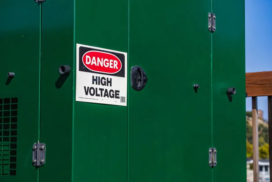
A high voltage tester is a bench or field instrument that generates a programmed stress voltage (typically 0.1 Hz VLF or 50/60 Hz AC) and applies it to a de-energised cable, motor or insulation sample; a clamp meter is a portable, single-hand current transformer that measures the magnetic field around a live conductor without breaking the circuit. The two sit on opposite ends of the electrical-test stack: the cable tester is the source of stress, the clamp meter is the observer of an already-energised system [S1][S3].
Use this rule of thumb on site: if the circuit must be locked out, isolated and earthed before you measure, you are in the high voltage tester domain; if you clip around a single live conductor and read amps in seconds, you are in the clamp meter domain. Conflating them (e.g. probing a 11 kV busbar with a 1000 V clamp, or using a VLF set to find a tripped breaker) is the most common procurement mistake and the most dangerous one.
Core Specifications Side by Side
The b2 electronics HVA34-1 and HVA34TD-1 portable VLF test sets output 34 kV peak / 24 kVrms, drive 1.5 μF of cable at 0.1 Hz, weigh 39 kg and are sealed to IP67 with the lid closed [S1]. The smaller HVA28 / HVA28TD units sit at 29 kV peak / 21 kVrms, 0.5 μF @ 0.1 Hz @ 20 kVrms and 14 kg in the same IP67 enclosure [S2]. Both pairs include two independent earthing paths, an integrated 12 kV transient protection at 50 Hz, and on-board Tan Delta diagnostics compliant with IEEE 400.2-2013 (Monitored Withstand Test) [S1][S2].
A Fluke digital clamp meter, by contrast, is rated for measurement Category III 1000 V / Category IV 600 V typical, measures AC and DC current via a split-core Hall or iron-vane jaw (commonly 30–400 A ranges), and provides best-in-class noise-free readings in confined cabinets [S3]. The clamp meter is a measurement terminal, not a stress source, and its voltage measurement input is hard-limited by the test-lead rating and the CAT rating, not by the jaw.
Decision Matrix: Tester vs Clamp Meter
Compare the two instrument families on four procurement criteria: (1) function, (2) voltage class, (3) circuit state, and (4) compliance anchor. A VLF cable tester performs VLF, DC and sheath-withstand testing on de-energised cable at 28–34 kV peak with Tan Delta per IEEE 400.2-2013 [S1][S2]. A Fluke clamp meter measures up to 1000 V CAT III on live conductors, with current resolution down to 0.01 A on the low range and True-RMS on variable-frequency drives [S3].
On function, the tester is a programmable HV source with built-in load sensing; the clamp meter is a passive transducer plus voltmeter. On voltage class, the tester handles 21–34 kVrms on the output side while the clamp meter is limited to 1000 V measurement inputs. On circuit state, the tester requires locked-out, isolated and earthed cable; the clamp meter requires the conductor to remain energised and normally loaded. On compliance, the tester is built around IEEE 400.2-2013 for field withstand and Tan Delta, while the clamp meter is built around IEC 61010-1 over-voltage categories and IEC 61010-2-032 for current clamps [S1][S3].
If the test objective is a quantitative insulation health number (Tan δ in 10⁻³ units, leakage current in μA, capacitance in nF) on a paper/XLPE/EPR cable, specify a VLF test set. If the objective is a working-state reading of amps, volts, frequency or kW on a 400 V motor feeder, specify a True-RMS clamp meter. There is no single instrument that does both jobs to a useful accuracy, and any vendor that claims otherwise is overspec'ing the wrong tool.
Who Each Instrument Is For (and Who It Is Not For)
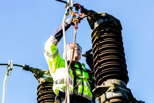
Specify a high voltage tester for: utility and industrial cable commissioning at 6–35 kV; after-fault re-energisation testing; periodic cable condition assessment on paper, XLPE, EPR or PILC insulation; sheath integrity testing with fault-locating mode; and OEM motor and generator winding hi-pot at the manufacturer's test bay [S1][S2]. A 14 kg HVA28TD is the right tool for a two-person crew that needs to walk a switchyard and test cable sections sequentially; a 39 kg HVA34TD-1 is the right tool for longer or higher-capacitance feeders up to 1.5 μF at 0.1 Hz [S1][S2].
Specify a clamp meter for: live troubleshooting of distribution boards, motor control centres and UPS outputs; load balancing across three-phase feeders; DC battery and PV string current checks; harmonic and inrush current capture on switching power supplies; and quick verification that a circuit is dead before applying lockout (in combination with a known-good voltage tester) [S3][S4]. A Fluke 377 FC-class clamp with FC wireless link to a phone is the typical 2026 spec for an instrumentation electrician doing both AC and DC work [S3].
A VLF tester is NOT for: live-circuit measurement (the unit generates the stress, it does not sample an external bus); low-voltage DC control wiring (the output is kV-class); or for any operator who has not been trained on the two independent earthing paths and the 12 kV transient protection. A clamp meter is NOT for: cable commissioning (it has no HV source); insulation resistance (use a [megger or insulation tester], not a clamp); nor for verifying absence of voltage above its CAT rating, even with the jaw closed (use a dedicated voltage tester rated for the system voltage) [S1][S3].
Selection Criteria When Sourcing a VLF Cable Tester
Lead with four numbers: peak output voltage (kV), load capability (μF at 0.1 Hz), weight (kg) and diagnostic scope. The HVA34TD-1 spec sheet quotes 34 kV peak, 1.5 μF @ 0.1 Hz @ 24 kVrms, 39 kg and full Tan Delta plus Monitored Withstand Test to IEEE 400.2-2013 [S1]. The HVA28TD quotes 29 kV peak, 0.5 μF @ 0.1 Hz @ 20 kVrms, 14 kg and the same diagnostic package [S2]. For a Chinese-market alternative, suppliers such as the Fuzrr (Fuzhou) range list ES3001P ground-resistivity testers and FR3010 digital clamp ground testers on the same catalogue page as their high-voltage instruments, but the actual VLF class for export-grade cable commissioning is still dominated by the Austrian and German OEMs [S1][S7].
Second, check safety: two independent earthing devices, electronic and mechanical discharging, plus a 12 kV transient protection system at 50 Hz are the minimum hardware baseline in the b2 electronics HVA series [S1][S2]. Third, check field readiness: IP67 with the lid closed, dry-type transformer (no oil, no arcing contacts, near-zero maintenance), USB and Bluetooth data download without an external PC [S1][S2]. Fourth, check the duty cycle: continuous (not thermally limited) operation is the published claim for the HVA28/34 families, which is what you want for sequential section testing on a long feeder [S1][S2].
For a bench comparison on cable-test sourcing and TDR level meter selection, the same spec-first logic applies: define voltage class, load, accuracy and standards reference, then reject any product sheet that does not put numbers against each line.
Selection Criteria When Sourcing a Clamp Meter
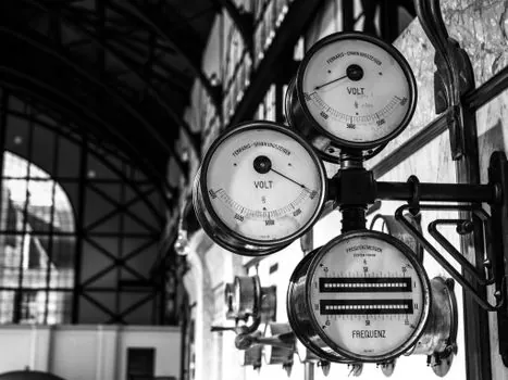
Lead with four numbers: AC current range and accuracy, DC current range (Hall effect vs fluxgate), True-RMS bandwidth, and safety category at the use voltage. Fluke's 2026 clamp-meter family spans 60 A to 2000 A AC, with iFlex flexible current probes extending the AC range to 2500 A on crowded busbars, and the 87V-class industrial multimeter clamp at 1000 V CAT III / 600 V CAT IV [S3]. A typical Amazon-listed non-contact AC voltage detector at the consumer end of the market runs 12–1000 V AC at sub-$20, with LED and beeper indication rather than a numeric reading [S4].
Second, jaw geometry: the 37 mm circular jaw on a Fluke 376/377 FC opens over a single 240 mm² cable or a 400 A busbar without crowding; the smaller 30 mm jaws on a Fluke 323 handle 400 A AC only and drop DC measurement entirely [S3]. Third, connectivity: FC wireless link to a Fluke Connect phone app logs every reading with a timestamp, which is the single most useful feature for an audit trail. Fourth, specialty functions: inrush current capture for motor starts, low-pass filter for VFD output at 50/60/400 Hz, and leakage-current measurement down to 0.01 A on the Fluke 369 FC [S3].
For earth-ground work, the Chinese ETCR2000 / ETCR2100 clamp-on ground resistance testers and the Fuzrr FR2000+ series measure ground resistance without disconnecting the electrode, but they are a different product class from a general AC/DC clamp meter and should be specified against the actual ground-electrode impedance, not the live-circuit current [S6][S7].
Real Use Cases on Site
Case 1 (VLF): A 11 kV XLPE feeder between two substations has failed twice in 12 months; the crew isolates the cable, applies 3 × U₀ = 19.1 kVrms at 0.1 Hz from an HVA34-1 for 15 minutes (per IEEE 400.2-2013), then runs a Tan Delta sweep from 0.5 × U₀ to 1.5 × U₀ on the HVA34TD-1 to grade the remaining insulation life [S1]. Result: a quantitative Tip-Up number and a go/no-go for re-energisation.
Case 2 (clamp meter): A 400 V motor control centre feeder is tripping intermittently; the electrician clips a Fluke 378 FC around phase L1, logs current over 8 hours via Bluetooth, and confirms the inrush at start exceeds the breaker curve by 15% [S3]. Result: a logged data file, not a guess, plus a recommended breaker setting change.
Case 3 (mixed): Before any VLF test, the same crew uses a non-contact voltage tester to confirm the cable is dead, then applies a temporary earth, then connects the VLF leads; the non-contact pen is the last sanity check before the VLF unit goes live, and it is a separate, <$20 tool with a 12–1000 V AC detection range, not the 1000 V CAT III clamp meter [S4].
Limitations, Failure Modes and Safety Anchors
VLF testers fail in predictable ways: (1) output cable or termination breakdown at the connector under wet conditions, mitigated by IP67 cases and the dry-type transformer; (2) incorrect load model used by the operator (capacitance higher than rated 1.5 μF on the HVA34, or 0.5 μF on the HVA28), which trips the internal limit; (3) loss of the second independent earth path, which removes the mechanical discharge backup and is the single most common field-failure root cause [S1][S2]. The IEEE 400.2-2013 Monitored Withstand Test combines withstand and Tan Delta into a single 15-minute procedure to reduce false passes on cables that would have failed a pure withstand test [S1].
Clamp meters fail differently: (1) jaw contamination on an open-core Hall unit produces a DC zero offset; (2) single-conductor clamping (clipping over both live and neutral together gives zero net field) gives a misleading 0.0 A reading; (3) measurement above the CAT III 1000 V rating on the test-lead input, even with the jaw closed, violates IEC 61010-1 and is the most common cause of arc-flash incidents during clamp-meter use [S3]. The Fluke product family addresses (3) by rating every input pair against a specific category and printing it on the silicone boot [S3].
Procurement Signals and Trackable Items
Trackable signal 1: the HVA28TD at 14 kg remains the lightest VLF + Tan Delta set on the public DirectIndustry catalogue as of the 2026-01 product update, with a quoted 0.5 μF @ 0.1 Hz @ 20 kVrms load and IEEE 400.2-2013 Monitored Withstand Test compliance [S2]. Trackable signal 2: the Fluke clamp-meter catalogue page was refreshed 2026-08-03 with the FC wireless family and iFlex probes called out as the 2026 workhorse for motor and VFD work [S3]. Trackable signal 3: b2 electronics GmbH is exhibiting the HVA series at Middle East Energy 2026, Hall H2 Stand C21, 1–3 September 2026 in Dubai, which is the next public window for hands-on comparison of VLF output and TD diagnostics [S1].
For component-level specifications, see pipe clamp.
