
An electrical fire monitoring system should combine residual-current detection, temperature monitoring, addressable reporting, and an independent control panel to identify faults before a developing fire becomes destructive [S1][S3].
The correct scope depends on the distribution boards being protected, the fault risks at each load, the required alarm threshold, and whether the panel must notify a central station or a local fire-alarm system [S1][S2].
Define the electrical fire monitoring scope
An electrical fire monitoring system is an independent subsystem of a fire-alarm system rather than a replacement for smoke, flame, or conventional fire detection. Its basic architecture comprises a monitoring panel, residual-current electrical fire monitoring detectors, and combined electrical fire monitoring detectors [S1]. The broader detection chain includes initiating devices, a controller, notification or suppression activation, and the initiating circuitry that links them [S4].
This distinction determines what the system can do. Residual current and temperature measurements identify deteriorating electrical conditions, while smoke or flame detectors identify products of combustion. A complete fire-protection design may therefore combine an electrical fire monitor with conventional initiating devices, notification appliances, and any required suppression interface.
For industrial buyers, the protection boundary should be listed circuit by circuit. One listed product uses 8 channels and accepts both residual-current and high-temperature inputs, with the relevant distribution-board loops routed into the combined detector [S1]. That channel count is a product-specific capacity, not a general design rule, so it must be checked against the number of protected circuits and the required reserve capacity.
Select residual current, temperature, or combined detection
Residual-current-only monitoring is appropriate when the main electrical risk is current leakage and the thermal condition of each circuit is already covered elsewhere. Combined monitoring is the stronger choice when one enclosure contains circuits exposed to both leakage and overheating. A temperature-only arrangement is narrower and should be justified by the monitored equipment and protection design [S1][S3].
The comparison is straightforward. Residual-current sensing detects leakage without directly measuring conductor temperature, making it economical for distributed circuits but incomplete as a thermal safeguard. Temperature sensing reveals heat changes in equipment, but it does not provide the same leakage information. Combined sensing covers both fault modes in one distribution-board device and provides a clearer basis for panel-level alarming [S1][S3].
Sensor selection must also account for the monitored line frequency. The cited combined detector is rated for 50 Hz/60 Hz lines and measures 92 mm × 59 mm × 110 mm, which makes installation geometry a direct selection criterion rather than an afterthought [S1]. For temperature-only installations, the relevant engineering background is covered in temperature monitoring, including the need to identify the actual thermal measurement point.
Match panel capacity, addresses, and communications
Panel capacity must exceed the connected detector count and the planned expansion reserve, while the communication topology must be physically compatible with every detector. A cited electrical monitoring panel supports 1 loop or 2 loops and works with DH12A, DH01B, and DH230 detectors, each of which uses an independent coded address for alarm reporting [S1].
Bus architecture is the next decision. One listed combined detector uses two non-polar buses, with the same conductors carrying communication and power, and supports a line frequency of 50 Hz/60 Hz [S1]. The power monitoring system that receives these signals must preserve device addressing, normal-status reporting, and alarm-status reporting, including a clear fault indication for a disconnected or inactive detector.
Installers also need to verify cable type, polarity independence, termination, address programming, panel compatibility, and the method used to set the residual-current alarm value. A standalone product claim is not enough: a detector that supports 8 input channels is not usable with a panel unless the panel supports that detector, its addressing method, and the required bus loading [S1].
Set thresholds around the equipment, not a generic alarm value
Alarm thresholds should be assigned from the normal leakage and temperature behavior of the protected equipment, installation conditions, and the protection strategy. Residual-current thresholds and temperature limits are design settings, not universal values, and a listed detector can be assigned its residual-current alarm value from the TC-5600 panel [S1].
Three variables must be separated. The measurement threshold is the condition that produces an alarm. The operating delay is the time allowed before escalation. The reset policy determines whether the system latches, resets automatically, or requires operator acknowledgment. A credible specification should state all three for every detector class.
Electrical fire monitoring can provide early warning for current leakage, temperature variation, and short-circuit-related heating, but continuous monitoring does not remove the need for correct protection design. Honeywell identifies equipment faults, defective or non-standard products, harmonics, poor connections and earthing, voltage surges, excessive thermal insulation, overloads, and new loads on old wiring among the electrical fire risks that can precede a hazardous event [S3]. The monitoring system is therefore a supplementary early-warning layer, not a substitute for protective conductors, correct earthing, suitable overcurrent protection, or safe installation practice.
Compare standalone, integrated, and centrally monitored options
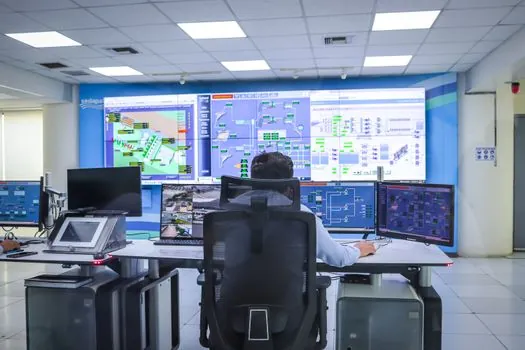
A standalone local system fits installations that require panel-level indication and local audible or visual alarms without a central monitoring service. An integrated installation connects the electrical fire subsystem to the building fire-alarm architecture, allowing alarm information to be handled within a broader control and notification arrangement. A centrally monitored option adds a 24/7 service that tracks alarms, verifies the emergency, and notifies first responders [S2].
Across cost, local response, and central coverage, the practical distinction is straightforward. A local panel gives immediate information at the protected equipment but does not itself provide constant external response. A central service adds continuous oversight and emergency escalation, with commercial monitoring commonly priced at $44 to $70 per month [S2]. Integrated systems provide a coordinated alarm path, but they introduce interface and acceptance-of-service dependencies that a standalone panel avoids.
Wireless communication is an option for the broader fire-alarm notification path, not a substitute for electrical sensing. One cited mesh network supports up to 8 connection paths and reports alarms in 2 seconds, compared with 45 seconds for the described dial-up method, while performing system checks every few seconds instead of once every 24 hours [S2]. Those figures belong to that communication architecture and should not be transferred automatically to an electrical fire monitoring bus or panel.
Verify service, integration, and compliance responsibilities
Supplier selection should be checked against service coverage, installation experience, local-code knowledge, and the ability to integrate maintenance and monitoring. Commercial fire-alarm providers should demonstrate relevant accreditation, experienced response technicians, local customer references, knowledgeable installers, and integration capability with security and other building systems [S2].
Two communication lines are not automatically required for every fire-alarm installation. Wireless alternatives can replace two telephone-line paths, including at sites retrofitting an existing system, provided the selected architecture satisfies the applicable local fire-code and acceptance requirements [S2]. The procurement team must identify who holds that compliance responsibility, who performs acceptance tests, and who documents alarm transmission, local indication, backup power, and fault response.
For larger systems, evaluate the monitoring scope as a power monitoring system function, with event status available to operators and an auditable link to fire response. A microcomputer protection relay may support protection-related decisions, but it should not be confused with the independent electrical fire monitoring panel, which receives detector status and manages the dedicated fire-monitoring function [S1].
Use a shortlist based on measurable acceptance criteria
The shortlist should retain only systems that satisfy six measurable conditions: coverage of every selected distribution board, residual-current and temperature functions where required, supported detector and panel models, sufficient loop and channel capacity, documented bus and addressing compatibility, and a defined alarm-to-response workflow [S1][S2].
For each candidate, request a point schedule showing detector model, protected circuit, channel, threshold, delay, notification method, address, and panel capacity. Add a 1 loop or 2 loop requirement when the application needs redundant loop capacity, and include an expansion allowance based on the approved design rather than an arbitrary percentage [S1].
Final acceptance should test normal status, residual-current alarm, temperature alarm, combined alarm, power loss, communications failure, and reset behavior. A commercially monitored installation also needs a documented route from alarm receipt to emergency notification, with local code, insurance, and authority-having-jurisdiction requirements resolved before purchase [S2].
For wider electrical-condition context, compare fixed-limit and phase-comparison approaches in phase-comparison versus fixed-limit alarms, but retain the core rule: select the electrical fire monitoring system from verified sensor duty, panel and bus compatibility, threshold logic, and a named monitoring responsibility.