
Lost foam casting (LFC) line selection is governed by four interlocking spec levers: pattern foam density (typically 16-25 kg/m³ for EPS), refractory coating permeability, sand compaction/vacuum level, and the reactivity of the molten metal against polystyrene pyrolysis products [S1][S2].
The line is not a single machine but a coupled chain — foam pattern shop, dipping/drying station, sand-fill flask on a molding line, vacuum-assisted pouring table, and shakeout — and procurement decisions made on any one station cascade into the others [S1]. Buyers who scope it as a "furnace + table" package routinely overrun by 25-40% on pattern defect rates.
Pattern Foam Grade and Density: Where the Casting Is Actually Defined
Polystyrene (EPS) foam pattern density is the first spec band, and it directly controls both dimensional accuracy and the pyrolysis gas load that the coating must vent. Standard automotive-class LFC patterns sit in the 16-25 kg/m³ range; lower density collapses under sand compaction pressure, higher density increases carbon residue at the metal-foam interface [S1][S2].
Low-carbon steel LFC studies explicitly compare four foam variants to isolate the carbon-contamination mechanism, and the conclusion is that foam grade — not just density — drives the surface carbon pickup that produces the dark "fold" defects visible on machined castings [S2]. When the buyer is sourcing for steel grades above 0.25 wt-% C, specify the foam supplier and lot-traceability up front; the foam itself is a metallurgical input, not a consumable.
Refractory Coating: Permeability Beats Thickness
Coating specification is the second lever, and it is the one most often mis-scoped as a paint-thickness call. In lost foam work the relevant spec is permeability (typically reported as a gas-flow number on a standard test patch) and refractory filler type, not dry-film thickness alone; the coating has to vent ~80-120 L of pyrolysis gas per kg of poured metal in the first 3-5 seconds after pour [S1].
A second function the coating performs is insulating the foam long enough for the metal front to advance without collapsing the pattern. Buyers should require the coating supplier to publish both permeability and a minimum wet-strike thickness range, and should validate it on a 1:1 test coupon of the heaviest section the line will pour. Coating recipes that pass a thin-wall test coupon frequently fail on a 30+ mm section, so do not extrapolate.
Sand Fill, Vacuum and the Molding Line Itself
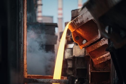
The molding station is the mechanical heart of the LFC line, and the choice is between a simple vibrating table and a vacuum-assist flask line coupled to a continuous conveyor of flasks. For steel and dense iron work the vacuum option is effectively mandatory: the negative pressure (commonly 0.03-0.05 MPa) holds the unbonded sand against the pattern during pour, and without it the foam wall deflects and the casting geometry drifts 1-3 mm [S1].
Sand media is silica (round-grain, AFS 50-70 typical) for ferrous work and chromite or olivine added in critical sections; the line must include sand cooling because recycled sand arriving back at the flask above ~60 °C deforms the foam pattern on contact. For high-volume automotive cylinder head and crankcase lines, the automatic molding line variant with flask indexing under 30 s/cycle is the spec band, and it is the same architecture covered in the parallel selection notes for flask size, sand rate and cycle spec bands.
Metal Reactivity, Pour Temperature and Gassing Defects
Aluminum LFC is governed by a different problem set than steel LFC. The aluminum melt reacts aggressively with the polystyrene pyrolysis products, and the resulting gas porosity is severe enough that pressurization during solidification has been studied as a direct countermeasure — published results show density and mechanical-property recovery when solidifying under applied pressure versus atmospheric pour [S3].
For aluminum, pour temperature is typically held in the 680-740 °C window depending on alloy, and a cover flux plus down-sprue filter is standard; for low-carbon steel the pour is hotter (1540-1620 °C) and the line-frequency induction furnace is the common melting source because it gives the bath volume control a batch furnace cannot [S1][S2]. The buyer should match the metal reactivity to the chosen line variant — quoting one line for both steel and aluminum at full duty cycle is a known source of pattern-shop redesign after commissioning.
Decision Matrix: Line Type vs. Workload

Three line architectures cover ~90% of LFC procurement: (a) manual flask + vibrating table for prototyping and runs under 200 castings/day, where capex is low and pattern flexibility is high; (b) semi-automatic flask conveyor with vacuum and coated-dip station for mid-volume 200-1500 castings/day in iron and small steel parts; (c) fully automatic indexed molding line with robotic coating and pouring for high-mix automotive cylinder blocks/heads above 1500 castings/day [S1].
Selection criteria reduce to four numbers: daily casting count, heaviest section thickness (drives coating permeability and pour temperature), alloy system (drives the foam grade and the gassing-defect countermeasure), and pattern changeover frequency (drives conveyor vs. batch flask). Where any one of those four drifts by more than 30% from the design point, the line will underperform on the metric that was compromised — usually scrap rate, not throughput.
Limitations, Failure Modes and When NOT to Specify LFC
LFC is the wrong choice when the part requires < 0.5 mm tolerance on features below 5 mm wall, when the alloy is magnesium or high-manganese (extensive foam-metal reaction), or when lot size is below ~50 castings/year and pattern tooling amortization cannot be spread [S1][S3].
The two dominant field failure modes are (1) carbon-related defects in low-carbon steel castings traced back to foam grade and coating permeability rather than pour practice [S2], and (2) gas pinhole and micro-shrinkage in aluminum tied to foam pyrolysis products and slow solidification [S3]. A line that does not have a documented incoming-foam inspection and a documented coating permeability check is operating with a metallurgical variable uncontrolled.
Standards, Sourcing and the Next Verification Step
There is no single ISO or ASTM standard that covers an entire LFC line; pattern foam is commonly specified against ASTM D1621/D1622 for density and compressive behaviour, refractory coatings against ISO 13778 for permeability, and sand media against AFS grading. Buyers should request these references in the technical schedule rather than generic "per OEM standard" language. [S1]
Two trackable signals for the next 60-90 days: (1) confirm whether the quoted line includes in-line sand cooling, because recycled-sand temperature above ~60 °C is the single most common commissioning delay in ferrous LFC; (2) request the foam supplier's batch certificate (density, bead size, blowing-agent residual) for the last three shipments, which is the cleanest leading indicator of pattern defect rate before the first pour.