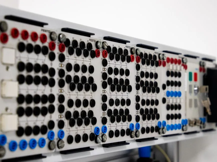
A modern ANSI 49 thermal element in a microprocessor-based motor protection relay combines a current-driven first-order thermal model with measured stator temperature from 100 Ω Pt RTDs, a function termed RTD biasing in vendor literature [S1][S4].
The bias closes the gap between the relay's calculated thermal capacity and the real stator temperature when the current-only model drifts, for example under elevated ambient, blocked ventilation, or unusual load profiles, allowing the motor to run closer to its insulation limit without unnecessary trips [S2][S4].
Why a current-only thermal model falls short
The thermal model in a microprocessor relay treats the motor as a first-order thermal mass heated by I²R losses, integrated against cooling time constants to produce a "thermal capacity used" register (0 to 100%), which trips near 100% and alarms near 90% on devices like the Multilin 269/369/460 [S3]. The same model biases heating upward when negative-sequence currents appear, because I₂²R in the rotor produces rotor heating that stator current alone will not reveal until damage is already done [S3]. What the current-only model cannot see is hot ambient, a missing or slipping fan cover, blocked cooling fins, or unusual duty cycle, all of which push actual stator temperature above what I²R integration would predict [S4]. Insulation class sets the ceiling that the model tries to respect: Class A 105 °C, Class B 130 °C, Class F 155 °C, Class H 180 °C, with allowable temperature rise above 40 °C ambient depending on the 1.0 or 1.15 service factor [S4].
What RTD biasing actually does inside the relay
RTD biasing is feedback of measured stator temperature into the thermal model: the relay's thermal-capacity register is adjusted up or down based on the RTD reading, so the current-based calculation is no longer running open-loop [S4]. Vendor documentation for the GE Multilin 469 states the thermal overload curves are "based solely on measured current, assuming a normal 40 °C ambient and normal motor cooling", and instructs the user to enable RTD bias "to augment the thermal model calculation of Thermal Capacity Used, if the motor stator has embedded RTDs" [S4]. The same biasing concept is shown in GE Vernova motor protection theory documentation, where the thermal model is explicitly "biased by the RTD's temperature feedback" to handle unusual operating conditions [S5]. The technique is a vendor-neutral feature, not a single relay's quirk: it appears in SEL technical literature on dual first-order thermal models [S6] and in field reports on the SEL 710 thermal capacity unit (TCU) [S7].
RTD selection, voting, and trip architecture
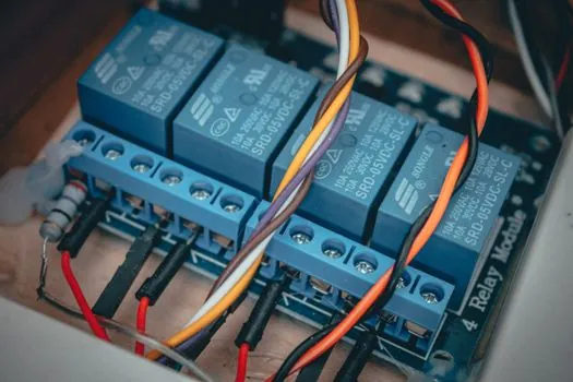
The Multilin 469 supports 12 programmable RTD inputs with four RTD types, each input configurable at three operational levels (alarm, high alarm, trip), plus RTD trip voting and open/short RTD failure alarms [S4]. Voting logic is the protection layer: if a stator is fitted with multiple embedded RTDs, the relay averages the reading and discards an outlier, so a single failed or shorted RTD cannot force a trip or block a trip that should have happened [S3]. On Multilin 269/369/460 relays, the bias is gated by an explicit "Bias the Thermal Model" selection in the RTD add-on module setup; with bias enabled, the RTD-derived algorithm alters the current-based thermal image rather than operating in parallel to it [S3]. The 100 Ω Pt (platinum, α = 0.00385 Ω/Ω/°C) RTD is the dominant stator probe across the documentation, with each channel programmable for sensor type, trip temperature, trip pickup delay, and trip dropout delay in seconds [S4].
Why RTD biasing is a slow-loop correction, not a fast one
RTDs are physically slow: their response time constants, typically 3 to 10 seconds for an embedded stator 100 Ω Pt element depending on housing and bonding, are far slower than the millisecond-scale current measurement inside the relay [S4]. This is why RTD bias is described as useful for "slow motor heating", such as gradual ambient rise, cooling-air loss, or chronic overloading near FLA, while starting, locked-rotor, and heavy short-term overloads remain the province of the current-based thermal element and the thermal relay trip curve [S4]. For a normal-duty induction motor, the bias branch in the protection relay is best understood as drift correction, not a trip path: it nudges the thermal-capacity register so a motor running at 95% thermal capacity on current alone does not sit there indefinitely if the stator RTD is reading 10 to 15 °C above the model's prediction.
Comparison: current-only thermal model vs current-plus-RTD-bias
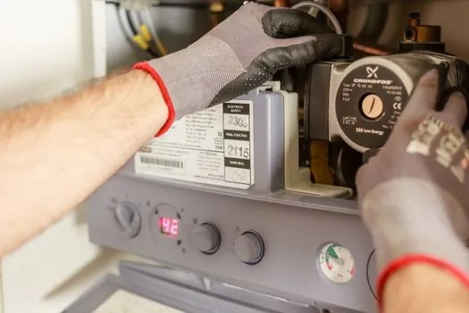
On a current-only thermal model, decisions are made from a single input (I, with negative-sequence bias), so accuracy depends on the model coefficients and ambient assumption (default 40 °C) [S3][S4]. With current plus RTD bias, the same model is recalibrated against the real stator temperature each RTD scan, and voting rejects single-sensor faults before they can take the relay down [S3][S4]. For high-inertia loads where locked-rotor and start thermal capacity dominate, a current-only or dual first-order thermal model still leads, and RTD bias adds little during the first few seconds of a start; see the Motor Protection Relay Trip Class for Normal Duty vs High-Inertia Loads reference for the corresponding trip-class selection. For duty near FLA with variable ambient or compromised cooling, RTD biasing allows a tighter setting and higher asset utilization, and the trade-off is that embedded stator RTDs are an additional failure mode the relay must supervise. Hot vs cold safe-stall time, covered in Motor thermal overload relay: hot vs cold safe stall time setting, is a separate ANSI 49 setting that interacts with, but is not replaced by, RTD biasing.
Limits, failure modes, and standards context
Rotor heating from negative-sequence currents remains invisible to any stator RTD until the rotor temperature rise has conducted through the air gap and into the stator body, which is why unbalance bias of the thermal model is implemented in current and runs in parallel to RTD bias rather than being replaced by it [S3]. Open or shorted RTDs on relays like the 469 generate a dedicated failure alarm and are typically excluded from voting by their own self-test, so a single RTD failure degrades the bias to "current model plus N-1 RTDs" rather than to a hard fault [S4]. Embedded stator RTD Pt100 elements are specified for trip temperatures keyed to the motor's insulation class (e.g. 130 °C alarm / 155 °C trip for Class F is a common engineering target; exact setpoints must come from the motor nameplate and OEM instruction), and they should be treated as advisory to, not a replacement for, the locked-rotor and acceleration protections in the microcomputer protection relay. Two trackable signals: first, new ANSI 49 publications and IEEE Industry Applications Society papers (e.g. DOI 10.1109/IAS.2011.6074475, October 2011) [S1] that update the thermal model alongside RTD bias; second, vendor firmware and instruction manuals for the Multilin 469, 369, 460, and SEL 710 family, which publish the exact bias-gain, voting, and trip-temperature registers that engineers need to configure for their motor's insulation class [S3][S4][S7].