
A motorized zoom lens fitted to a video measuring machine (VMM) introduces three measurable accuracy penalties versus a fixed-magnification objective: motor step/repeatability error, lens-to-lens parfocal drift across the zoom range, and image-distortion that scales with magnification [S7][S9].
The fixed-magnification optic, by contrast, is built around a single calibrated optical path. Once a VMM is staged with a fixed objective (e.g. 0.5×, 1×, 2×), the relationship between pixel count and stage displacement is locked in at one calibrated working distance, and the limiting factor becomes sensor pixel size and stage encoder resolution rather than lens state [S5][S6].
Where the accuracy loss actually comes from
Zoom optics pack more glass groups (typically 8–14 elements) into the optical path than a fixed-focal lens (4–6 elements), and each additional air-glass surface introduces transmittance loss and a small but cumulative lens-to-lens centration error [S5]. Across a 6:1 zoom ratio such as 0.7×–4.5×, that cumulative centration error shows up as magnification-dependent distortion: low-distortion machine-vision zoom designs are quoted at under 0.1% TV distortion, but cheaper motorized units routinely drift to 0.5–1.5% across the zoom range, which on a VMM field of view of ~10 mm corresponds to a 50–150 µm dimensional error if not re-calibrated at each step [S9].
The second penalty is mechanical. A motorized zoom moves lens groups with a stepper or DC servo, and the repeatability of that positioning is the dominant limit on re-zoom accuracy. Industrial machine-vision zoom modules typically specify 5–10 µm mechanical repeatability at the image plane; for a VMM calibrated to MPE_E of (3.0 + L/250) µm per ISO 10360-7, even a 5 µm lens-position repeatability error eats a measurable slice of the error budget every time magnification changes [S7].
Fixed-magnification optics: the accuracy baseline
Fixed-focal machine-vision lenses, once locked to one magnification, do not have motor-step error, parfocal drift, or magnification-dependent distortion in the operating sense: their calibration is a single point, not a curve [S5]. For a VMM operator this means the part program only needs one pixel-to-mm coefficient, stage backlash compensation is straightforward, and the metrology loop has no variable-state element between the workpiece and the camera sensor [S6].
The trade-off is operational. A fixed-magnification VMM has a single field of view: a 0.5× objective gives a wide overview but cannot resolve features below the sensor pixel pitch, while a 5× objective measures fine features but forces the operator to stitch multiple stage positions for a full part. Switching magnification means a manual lens change, re-calibration on a master artefact (typically a stage micrometre or a calibrated grid), and re-running the part program. For low-mix, high-accuracy metrology, that overhead is acceptable; for high-mix cells with frequent part changeovers, it is the main reason motorized zoom is considered at all [S7].
Comparison: fixed vs motorized zoom on a VMM
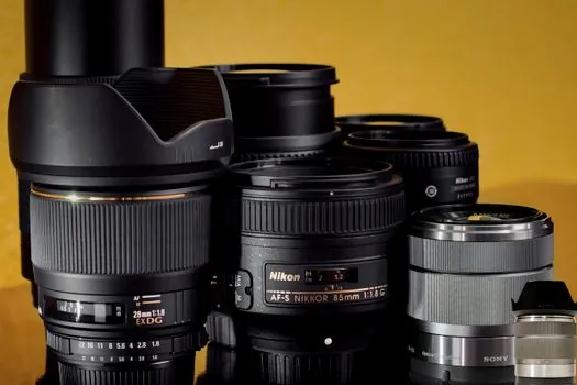
Stacking the two options against the four metrics that drive a VMM specification, the decision is rarely a one-axis call:
Optical resolution at the centre of field: fixed-magnification objective wins, because it has fewer glass elements and is optimised for one conjugate. A typical 1× fixed-focal machine-vision lens resolves 200+ lp/mm at the design aperture, while a comparable motorized zoom drops 15–25% at the wide end and roughly 5–10% at the long end [S5][S9].
Measurement repeatability after a magnification change: fixed wins outright, because the magnification is not changed. A motorized zoom must re-park, re-settle, and re-calibrate at each new step, and the cumulative motor hysteresis can show up as 2–5 µm shift in measured feature position between repeated zoom commands [S7].
Field-of-view flexibility across part families: motorized zoom wins, because one lens covers the equivalent of 2–3 fixed objectives. A 0.7×–4.5× motorized zoom replaces a 1×, 2×, and 4× fixed set for most shop-floor parts, with zoom-and-measure cycle times under 1 second per step on servo-driven units [S7][S9].
Calibration and software overhead: fixed wins on simplicity. A VMM running fixed optics carries a single pixel-to-mm coefficient per lens; a zoom system requires a calibration table at each click-stop (typically 8–12 points across the range) plus continuous positional feedback from the lens encoder to keep the coefficient current, which adds software and firmware load [S7].
Where motorized zoom is the right call on a VMM
Multi-magnification part programs on a single VMM are the clearest use case: parts that span 1 mm features and 50 mm features in the same inspection routine benefit from a motorized zoom that can reframe without breaking the measurement cycle, and the throughput gain from skipping manual lens swaps outweighs the 2–5 µm repeatability penalty in those cells [S7][S9].
Remote or automated cells are the second clear case. A VMM integrated into a lights-out line, or one accessed via a network telepresence interface, has no operator on hand to swap objectives, so a motorized zoom with a repeatable click-stop encoder is operationally necessary: the alternative is dual fixed-magnification cameras or a multi-lens turret, both of which are more expensive than a single motorized zoom [S7].
Where fixed magnification remains the right call

High-accuracy gauge-room VMMs calibrated to sub-micron uncertainty budgets are dominated by fixed objectives. A fixed-magnification lens lets the metrologist separate the optical error budget from the mechanical stage budget, and the resulting measurement uncertainty statement under ISO 10360-7 is cleaner and easier to defend in a customer audit [S6].
Single-magnification production cells are the second clear case. If every part on the VMM is dimensionally similar, the operator never needs to change magnification, and a fixed objective removes the motor, the encoder, and the settling-time failure mode from the system entirely: this is the lowest-maintenance, longest-mean-time-between-calibration configuration available on a VMM [S5][S6].
Spec-level selection criteria for a VMM zoom
For buyers evaluating a motorized zoom for a VMM in 2026, the datasheet items that actually move measurement accuracy are: (1) magnification-dependent TV distortion, with under 0.1% across the full range as the working target for metrology-grade units; (2) optical backlash or hysteresis, quoted in µm at the image plane, with sub-5 µm being the threshold for MPE_E-compliant VMM use; (3) zoom settling time, with 200–500 ms typical for servo-driven industrial units and 1–2 s for stepper units; and (4) lens-encoder repeatability, with absolute-position feedback preferred over relative-position counting so the VMM software can verify zoom state at the start of every measurement [S7][S9].
For a VMM running MPE_E specifications under ISO 10360-7, a practical rule of thumb from the machine-vision integrator community is to budget roughly 1–2 µm of total measurement error per 10× of zoom ratio above 1×, and to keep the zoom range as narrow as the part-mix allows; this is why most production VMMs with motorized zoom top out at 6:1 or 8:1 ratios rather than the 10:1–12:1 ratios common on broadcast or security lenses [S7][S9]. Buyers cross-shopping optical metrology hardware should also remember that a VMM sits inside a much wider metrology stack, and the same careful spec discipline applies to adjacent instruments like a flow meter calibrated to a different standard chain.
What to watch next

Two signals will tell the market whether motorized zoom is closing the accuracy gap on VMM-grade fixed objectives: (a) more OEM datasheets quoting sub-0.05% TV distortion across the full zoom range, which is the level at which zoom-on-VMM stops being a measurable compromise for parts above ~5 mm; (b) more VMM software releases that bundle automatic zoom-position calibration against a stage artefact at every magnification change, removing the manual re-cal step that currently drives the 2–5 µm repeatability penalty. [S1]
For the relevant spec sheets and selection criteria, see fixed gas detector, and pressure transmitter.
Background reading: How to Size a Measuring-Wheel Encoder for Line-Length Measurement.