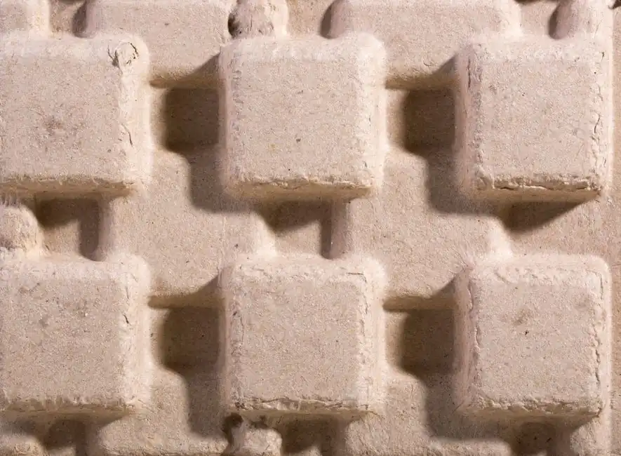
For castings above roughly 10 metric tons, pit molding is the only layout that absorbs casting depth and floor weight, while flask molding still wins on dimensional control, pattern handling, and shakeout economics [S1][S2].
The two methods are not rivals once you cross the threshold where a single flask pair would need to be fabricated from scratch; combining them, with flasks on the upper and lower sections and a sand-rammed pit in the middle, is now the standard workaround for single-piece or low-volume heavy castings in machine tool, turbine, and press frames [S2].
Where Each Method Stops Working on Its Own
A flask is a rigid metal or wood frame, usually supplied as an upper (cope) and lower (drag) pair, that contains molding sand, registers pattern halves through pins and bushings, and lets the closed mold be flipped, rolled, and lifted without losing geometry [S5]. For castings under a few hundred kilograms, flasks are cheap, replaceable, and can be fabricated by the foundry itself; hobby and job-shop builds in 12-32 inch squares are routinely made from 2x6 Douglas fir with 10-gauge corner angles, 3/4-inch birch plywood with 3/4 x 1/2-inch retaining strips, or channel iron for non-tapered prototypes [S4].
Pit molding drops the flask concept entirely. The mold cavity is formed directly in a refractory-lined pit in the foundry floor, with the pit walls acting as the flask. Pit depth is set by the casting's height plus a sand base, and the pit footprint is set by the casting's length and width plus ramming clearance. For an 18-metric-ton HT300 gray iron crossbeam measuring 15,000 x 1,800 x 1,650 mm, the foundry that produced it used a pit measuring 12 m x 6 m x 3 m to host the middle of a three-part mold, while conventional flasks handled the upper and lower sections [S2]. That same logic scales: anywhere a flask pair would have to be purpose-built, a pit already in the floor becomes the cheaper path.
Decision Matrix: Pit, Flask, or Hybrid
Selection is driven by five criteria: casting mass, dimensional tolerance, pattern cost, shakeout access, and capital. Below is the working matrix used by heavy-casting foundries. [S5]
1) Casting mass and size. Pure flask molding scales until the flask itself becomes a rigging problem; once a cope-drag pair exceeds roughly 2 m x 2 m and several tons, handling on jolt-squeeze machines becomes the bottleneck, and pit depth stops being a limitation because the floor is the flask [S1][S2]. 2) Dimensional tolerance. Flasks deliver tighter match because alignment pins and bushes fix the cope-drag relationship mechanically; pit sections rely on sand-to-pattern contact, so they trade tolerance for size [S5]. 3) Pattern cost. EPS (expanded polystyrene) board patterns are practical in the pit because they are disposable and cheap; flask sections justify more expensive wooden or metal patterns because the flask preserves geometry across pours [S2]. 4) Shakeout. Flask molds break down into a reusable container plus sand; pit molds are dug out, with the pit then re-leveled and re-bedded for the next pour [S2][S5]. 5) Capital. A basic jolt-squeeze flask machine is a lower single-machine investment than a flaskless high-pressure molding line, but flaskless lines win on cycle time (hundreds of molds per hour) and per-mold labor cost, so the flask approach is the default for large, heavy, low-volume work while flaskless is the default for small, high-volume work [S5].
For castings above 10 t where lead time and capital are both tight, the hybrid layout, flasks on the ends and pit in the middle, is the answer. The case-documented HT300 crossbeam was built in two months, in part because fabricating a single 15-meter flask would have consumed a month on its own [S2].
Process Design for the Hybrid Layout
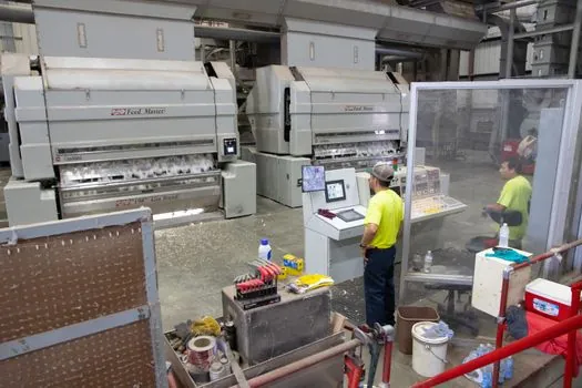
Three-part molding is the working pattern when a pit fills the center. The parting planes are set first, the upper and lower flask sections are rammed in resin sand around wood patterns, and the pit is leveled with a resin-sand base before the lower flask is lowered into position [S2]. For the 18-ton crossbeam, EPS board formed the pit-side pattern because the geometry was single-piece; sand was rammed around the EPS using the pit walls as two boundaries and timber boards as the other two [S2].
Gating for very large castings follows the high-flow, low-velocity rule. Four identical gating sets (sprue, runner, branch sprue, ingates) were placed two at each end and two at the mid-section, distributing fill across the 15-meter length and avoiding cold shuts and slag entrapment [S2]. Machining allowances on the same casting were set at 12 mm on the top surface and 10 mm on the bottom and sides, which is consistent with rough-machining stock left on large gray iron machine tool castings [S2]. For background on flask mechanics and how flasked molds differ from flaskless systems in cycle time and sand strength, the molding line overview and flask molding machine entries are useful starting points.
Failure Modes and Constraints
Three failure modes dominate hybrid and pit work. First, mold flotation: large pours of liquid iron generate buoyancy that can lift a flask off its seat if the flask is not weighted or mechanically locked, and the same effect can shear the sand-to-flask bond in a pit section if the ramming is too loose [S4]. Second, mismatch at the flask-pit interface: any step between the flask seat and the pit floor becomes a sand fin or a metal runner; a leveled resin-sand base under the lower flask and tight board restraints on the pit sides are the standard countermeasures [S2]. Third, EPS residue: if a pit-section EPS pattern is not vented or burned out cleanly, the gas load during pour can blow back through the melt and produce porosity; venting paths and controlled pour rate are therefore non-optional in EPS-pit layouts [S2].
Foundries also run into a fourth, less obvious limit: pit depth. Most existing pits in heavy foundries are 3-4 m deep, and going deeper costs reinforced walls, sump drainage, and a new liner. When a casting's height plus rigging plus sand base exceeds pit depth, a deeper pit is the only path, and that is typically the trigger for either an in-ground extension or a switch to a fully flasked, multi-part cope-drag stack above floor level [S1][S2].
Standards, Sourcing, and Who Should Use Which Method

Foundry process selection for very large castings is governed less by a single standard and more by the casting's own specification chain. Pattern allowances, machining stock, and dimensional tolerances are typically called out against ISO 8062 (CT-grade casting dimensional tolerance system) on the casting drawing, while molding media, sand testing, and binder systems are covered under the foundry's internal process sheets and customer-specific PPAP or FAI requirements. For very large castings in machine tool, ship, wind, and hydraulic press frames, the practical sourcing pattern is a foundry that owns a pit of at least 12 m x 6 m x 3 m and a flask inventory that can be paired with EPS or wood patterns on demand [S2].
Who should use pit molding: foundries running castings above 10 t, with single-piece or very-low-volume orders, where a flask of the required size would need to be built from scratch and where the casting's depth plus sand base fits inside an existing pit [S1][S2]. Who should use flask molding: any job where a flask of the right size already exists, where dimensional accuracy and shakeout repeatability matter, and where the casting mass is below the rigging limit of the foundry's overhead crane and rollover equipment [S5]. Who should use a hybrid layout: heavy-casting foundries that already own both flask pairs and a pit, running very large castings under tight lead time and without the budget to fabricate a single oversize flask [S2]. For a wider view of how flasked and flaskless molding lines compare in cycle time and sand economics, the automatic molding line and static-pressure molding machine pages lay out the equipment side. For a comparison of parting practice on the joint face itself, this parting powder field guide is a useful companion read.
Trackable signals to watch: foundry disclosures of pit depth and floor loading capacity (typically buried in their equipment lists rather than marketing pages), and a new generation of deeper reinforced pits designed for castings above 20 t in the wind and ship sectors. Pit depth plus flask inventory will remain the two binding constraints as castings get larger through 2026.
