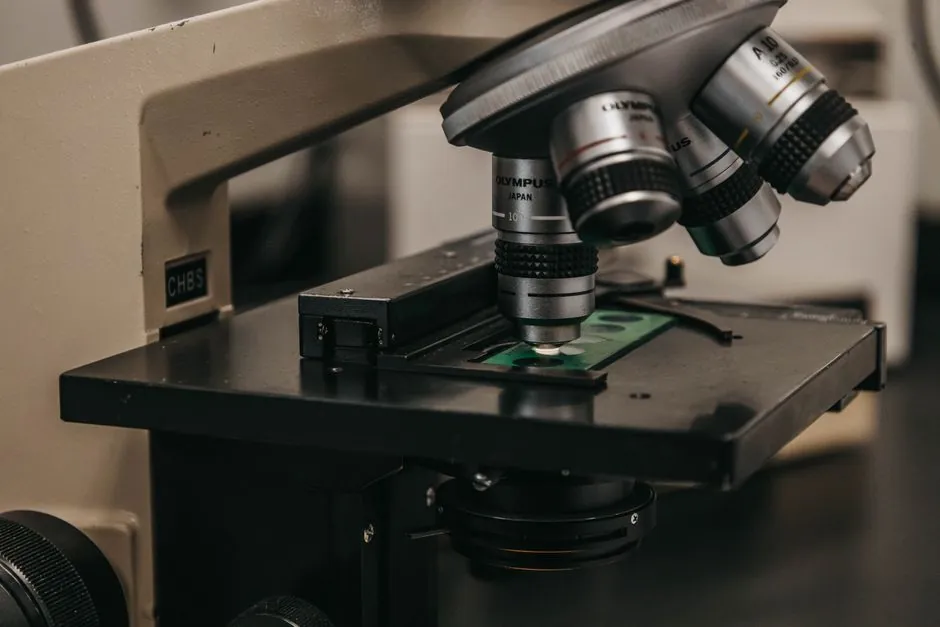
Potentiometric and optical displacement transducers use different sensing elements and practical resolution limits, so the better choice depends on contact risk, travel, surface condition and control architecture.
Potentiometers provide direct, accurate displacement measurement in automatic control and metrology, while optical methods cover non-contact configurations from triangulation to confocal and interferometry [S1][S2][S5].
Resolution starts with the sensing principle
Resolution is the smallest displacement change that the instrument can distinguish, and it must be separated from accuracy, linearity and repeatability when selecting a device [S4]. A potentiometer divides an applied voltage according to wiper position, with the output ratio determined by the fraction of the resistance track between the wiper and a fixed end [S3].
The physical track construction sets the first resolution boundary. Wire-wound potentiometers contact successive turns of a resistance coil, so their resolution is constrained by the spacing between turns. Carbon-film and conducting plastic-film tracks avoid that discrete turn structure and can theoretically reach a resolution of 10^-4 mm, although their practical performance is limited by slider construction and contact mechanics [S3].
Optical systems do not use a mechanical wiper, so their physical resolution depends on the optical method, target geometry and signal processing rather than resistance-track granularity. Available non-contact families include intensity measurement, triangulation, time of flight, confocal and interferometry [S5]. This distinction matters when a required increment is below the practical movement of a sliding contact or when contact would damage the measured surface.
Potentiometric resolution, life and failure mechanisms
Carbon-film potentiometers typically provide 5 million reversals, while conducting plastic-film units typically reach 30 million reversals; comparable wire-wound units are typically quoted at 1 million reversals [S3]. Plastic-film construction therefore combines better theoretical resolution with the highest life expectancy among those three constructions, although real installations still require verification of wiper pressure, track condition and motion profile.
Slider contact is the dominant weakness. Dirt below the wiper can raise contact resistance and create a false voltage, or it can interrupt the output completely. High slider speed can produce contact bounce and intermittent signals, while friction can alter the force required to move the measured body [S3]. These mechanisms affect usable resolution because a track may meet a voltage increment requirement in laboratory conditions but not after contamination, speed changes or repeated reversals.
Industrial selection should therefore include stroke, reversal rate, motion direction, environment and output interface, not just a quoted resolution. The selection criteria listed for displacement transducers include range, accuracy, resolution, response time, environment and output type [S4]. A potentiometer displacement sensor is well matched to a low-cost position loop with a sliding mechanical interface, provided that contact wear and contamination are included in maintenance planning.
Optical resolution is method-dependent, not a single number
Optical displacement measurement can be divided into at least five commercial sensing approaches: intensity-based, triangulation, time-of-flight, confocal and interferometric methods [S5]. The technique determines working range, surface compatibility, response behavior and the price-performance relationship, so a supplier claim of high resolution is meaningful only when the optical configuration and target are identified.
Confocal systems typically achieve higher axial resolution, while laser displacement systems can offer faster measurement operation with different resolution behavior. A 2026 technical comparison addresses 0.1 µm resolution on reflective surfaces, including the axial-resolution advantage and lateral scanning-speed limitation of confocal measurement [S7]. A 0.1 µm increment is 0.0001 mm, matching the theoretical order of magnitude cited for film-type potentiometers, but the two figures do not describe equivalent systems: one is an optical performance case, while the other is a potentiometric construction limit before mechanical and environmental degradation [S3][S7].
For engineering selection, the laser displacement sensor should be treated as a family rather than a universal resolution class. Surface reflectance, target angle, stand-off distance, spot size and ambient light all affect signal quality, while confocal systems add depth selectivity and axial discrimination. More detail on that split appears in the point versus line-spectral confocal displacement comparison.
Criterion-by-criterion technology comparison
On resolution, film potentiometers offer a theoretical 10^-4 mm limit, while confocal optical systems typically provide higher axial resolution and a reflective-surface comparison specifically addresses 0.1 µm performance [S3][S7]. On mechanical life, potentiometers are specified in reversals: 1 million for wire-wound, 5 million for carbon film and 30 million for plastic film, whereas optical sensors avoid direct wiper contact but require clean optics, stable alignment and a suitable target [S3][S4].
On cost and integration, a potentiometer is a passive resistive divider with a voltage output, making it straightforward to introduce into an analog control system. Optical transducers add light source, detector, signal conditioning and possibly coded-disk or confocal positioning, so their installation and commissioning requirements are more involved [S3][S4]. On environmental exposure, the potentiometric failure path is concentrated at the wiper-track interface, while the optical failure path includes contamination, alignment, ambient light and target interaction [S3][S5].
On measurement range, available industrial potentiometric examples extend from 0.25–1.65 mm on a 991 series sensor, 10–300 mm on an RC20 series sensor and 25–250 mm on an RC13 unit, with stated linearity varying by model [S2]. Optical range is method-dependent, and the research does not provide one defensible range that can be applied across intensity, triangulation, time-of-flight, confocal and interferometric systems [S5].
Application fit and practical selection

Use a potentiometric transducer when the measured member can tolerate a sliding contact, travel fits a defined resistive track, and simplicity of installation or analog integration outweighs contact-life concerns. It is a practical choice for automatic-control and metrology duties, but a resolution claim should be discounted when the wiper is slow, dirty, lightly loaded or subject to frequent reversal [S2][S3].
Use an optical transducer when contact is unacceptable, the target is accessible optically, or the required discrimination benefits from fine axial measurement. Confocal geometry is the stronger candidate when axial resolution is the controlling requirement, while other optical methods may be more suitable when response speed, working distance or target size governs the design [S1][S5][S7]. For reflective metal or plastic parts, verify the stated performance under the actual finish, color, angle and stand-off distance rather than relying on a generic 0.1 µm figure [S7].
Neither technology is the correct answer for every installation. A potentiometer is not the better choice for a fragile, dusty or continuously moving surface where wiper contact can contaminate or wear the target. An optical system is not the better choice when the target cannot be reliably illuminated or aligned, when the working environment attacks optics, or when the simplest possible analog input is the overriding requirement [S3][S5].
Procurement data to request before comparing instruments
Request separate data for rated range, resolution, accuracy, linearity, repeatability and response time, because a sensor with fine nominal resolution can still deliver poor position data through drift, noise, target variation or mechanical play [S4]. For potentiometers, include wiper-track construction, expected reversals, electrical output and mounting orientation. Available examples list linearity from 0.05% to 0.25% for certain 50–750 mm draw-wire models, 0.4% to 1% for a 40–130 mm series and operating temperatures of -40 °C to 85 °C for that latter series [S2].
For optical systems, require the method, working range, linearity, response rate, target material, target angle and ambient-light limits. A confocal specification should distinguish axial resolution from lateral resolution, because higher axial discrimination may come with reduced lateral scanning speed [S7]. This is also where an optical comparator may be relevant for geometric inspection, although its resolution requirement must be assessed separately from single-point displacement sensing.
A defensible comparison therefore uses the required displacement increment, stroke, reversal rate or scan rate, target condition and operating environment. Film potentiometers can reach a theoretical 10^-4 mm, typical life spans run from 1 million to 30 million reversals by construction, and the cited confocal-versus-laser case targets 0.1 µm on reflective surfaces [S3][S7]. Those figures give the screening limits, while field conditions determine the final selection.