
For industrial buyers and OEM design engineers, pressure sensor sizing follows a fixed order: pressure range first, reference type second, accuracy third, output and media last. Skipping the order is the root cause of most field failures, premature diaphragm fatigue, and warranty returns on hydraulic and pneumatic systems [S1][S2].
Selection is governed by five concrete numbers: full-scale (FS) pressure, proof pressure, burst pressure, accuracy band as percent of FS, and operating temperature window. Three pressure reference types cover roughly 90% of industrial use: gauge (PSIG), absolute (PSIA), and differential (ΔP), with sealed-gauge and compound variants for special cases [S1][S2][S5].
Range first: size FS to duty, proof to spikes, burst to safety
A sensor running at 80 to 100% of full scale most of the time will fail early from diaphragm fatigue, so the conservative engineering guideline is to keep normal operating pressure between 50% and 80% of FS [S8]. A hydraulic system at 300 PSI normal with 500 PSI spikes should be specified with a 500 to 600 PSI FS sensor, not 300 PSI [S1].
Proof pressure is the overpressure the sensor survives without permanent spec drift, and burst pressure is the rating at which the housing or diaphragm ruptures. Both numbers must be checked against water-hammer, pump pulsation, and valve slam events; proof pressure at 1.5 to 2 times FS and burst at 3 to 5 times FS is common in OEM datasheets [S1][S8]. The HVAC sizing table below shows how the same logic compresses to much smaller ranges, 0 to 250 Pa for air ducts and 0 to 50 bar for refrigerant lines, so the 50 to 80% rule still applies but with different unit scaling [S4].
Reference type: gauge, absolute, sealed-gauge, differential, compound
Gauge pressure sensors measure relative to local atmospheric pressure, so 0 barG equals the ambient barometric reading, and they are the default for hydraulic, pneumatic, pump, compressor, and HVAC-refrigerant service [S1][S2][S4]. Absolute pressure sensors measure against a sealed vacuum reference, so they are specified for barometric, altitude, vacuum, and environmental monitoring where ambient drift would corrupt the reading [S1][S2].
Differential pressure sensors measure Port 1 minus Port 2 and are the workhorse for filter-clog detection, airflow, VAV boxes, and cleanroom pressure cascade, where the signal of interest is a delta, not an absolute value [S1][S2][S4]. Sealed-gauge sensors are a hybrid with a factory-sealed reference near 1 bar, used where venting to atmosphere would invite moisture or contamination. Compound sensors span full vacuum on the negative side and positive pressure on the high side, the right pick for systems that cycle between vacuum and pressure such as vacuum pumps and laboratory HVAC [S5].
Accuracy, thermal error, and the percent-of-FS trap

Pressure sensor accuracy is almost always expressed as a percent of full scale, not percent of reading, and the difference matters: a ±0.25% FS sensor on a 1000 PSI range can drift ±2.5 PSI at any point in the range, and that same ±2.5 PSI at a 100 PSI working point is a 2.5% reading error [S1]. The HVAC duct case makes this sharper: a sensor ranged 0 to 250 Pa with ±0.25% FS is only ±0.625 Pa absolute, which is fine for fan tracking but useless for cleanroom cascade if the room spec is ±5 Pa [S1][S4].
Thermal effects on the zero and span add a second error budget, typically given as percent FS per °C or as a compensated temperature window. For OEM equipment that ships into uncontrolled field conditions, a wider compensated window (for example, -40 to +125°C) and a published total error band over that window are usually worth the small cost premium [S1][S3]. Where a sensor only monitors a non-critical trend, a looser accuracy spec (for example, ±1% FS) is acceptable; where it closes a control loop, ±0.25% FS or tighter is the safer default [S1].
Output signal: 4 to 20 mA, 0 to 10 V, ratiometric, and digital buses
Analog outputs dominate industrial wiring: 4 to 20 mA for long runs and noisy plants because current loops reject voltage drop, 0 to 10 V for short cabinet wiring, 0.5 to 4.5 V ratiometric for 5 VDC-powered OEM modules, and 0 to 5 V for legacy PLC cards [S1]. Digital outputs (I2C, SPI, RS485, Modbus) are standard on lower-power OEM modules and on board-mount MEMS pressure sensors, where the host controller can read higher resolution and apply linearization in software [S1].
For 24 V plant loops with a PLC or DCS, 4 to 20 mA remains the default because of noise immunity and the live-zero fault detection (a reading near 4 mA with a broken wire reads as 0 mA, which the controller can flag). When the spec already lists a digital fieldbus such as HART, PROFIBUS PA, or Foundation Fieldbus, the pressure transmitter is typically a smart device that overlays digital communication on the analog loop, not a replacement for it [S1][S2]. For remote and battery-powered monitoring, a Modbus RTU over RS485 or a wireless IoT sensor with a digital output is now a common OEM choice and worth comparing against the wiring cost of a 4 to 20 mA home run [S2].
Media compatibility: wetted materials decide survival

Wetted material selection (the diaphragm, port, and seal that touch the process fluid) is the decision that determines chemical compatibility, and it has to be matched to the medium before accuracy or output is even considered.
Stainless 316L is the safe default for general industrial fluids, but it is not universal. For HVAC and pneumatic service, brass ports with FKM seals are common and lower cost; for cleanroom and medical, a crevice-free 316L port with an EPDM or FFKM seal is the standard [S3][S4].
Comparison: 4 to 5 common reference types on buyer decision criteria
Choosing a reference type is a structured trade, not a preference. The four that cover most industrial duty are gauge, absolute, differential, and compound; sealed-gauge is a special case worth listing for OEM export equipment. Use the comparison below as a quick filter before pulling datasheets. [S1]
Gauge: best cost per point, ideal for hydraulic, pneumatic, pump, and HVAC-refrigerant service; reading drifts with local barometric change, so it is the wrong pick for altitude or barometric work [S1][S2][S4]. Absolute: best for vacuum, altitude, barometric, and any reading that must not move with weather; higher cost because of the sealed vacuum reference, but the reading is stable across elevation [S1][S2]. Differential: required for filter monitoring, VAV, cleanroom cascade, and flow; both ports are wetted, so media compatibility must be checked on both sides, not just the high side [S1][S2][S4]. Compound: the only correct pick for systems that swing across atmospheric, such as vacuum pumps and laboratory HVAC; specify VAC to rated positive pressure as a single range, for example VAC to 100 psig, and confirm the sensor can resolve both ends without a dead zone [S5]. Sealed-gauge: factory-sealed near 1 bar, useful where the process port cannot be vented to atmosphere; otherwise the gauge-type accuracy and cost story applies [S1][S2].
Selection walkthrough: HVAC, hydraulic, and vacuum worked examples
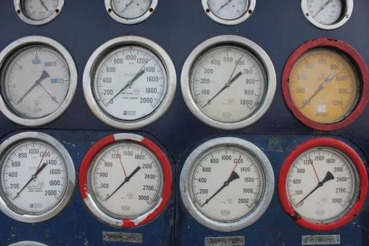
For HVAC duct static pressure, a differential sensor at 0 to 250 Pa with ±0.25% FS accuracy and 4 to 20 mA or 0 to 10 V output is the default. For refrigerant high-side, a gauge sensor at 0 to 50 bar with 316L wetted, 1.5 times FS proof pressure, and a -40 to +125°C compensated window covers most commercial chillers. For filter monitoring, a differential sensor at 0 to 1000 Pa is enough, and the output can be a 0 to 10 V signal that the BMS reads directly [S4].
For a hydraulic press at 3000 PSI normal with 4500 PSI spikes, size the FS at 5000 to 6000 PSI, the proof pressure at 1.5 times FS (7500 to 9000 PSI), and the burst at 3 times FS or higher; pair 316L wetted with FKM seals and a 4 to 20 mA output for plant wiring [S1][S3]. For a vacuum conveying line that pulls -14 psiG at deep vacuum and ramps to +30 psiG during blowback, specify a compound sensor ranged VAC to 50 psig, ±0.25% FS, 4 to 20 mA, with wetted material compatible with the conveyed powder's moisture and chemistry [S5].
Who should NOT pick the cheapest gauge sensor
If the process is a closed-loop control, if the working pressure sits below 20% of the sensor's full scale, or if the reading must remain stable across weather and elevation changes, a generic low-cost gauge sensor is the wrong pick. The same applies when the medium is corrosive, abrasive, or food-grade: a 316L default is no substitute for a verified material compatibility sheet, and an unrated seal will fail long before the diaphragm [S1][S3][S4].
The pressure sensor selection guide covers additional reference designs (thin-film, piezoresistive, ceramic, capacitive, piezoelectric) and where each technology earns its extra cost; the limit switch sizing map is a useful parallel for the same five-step methodology applied to a different sensor family.
Trackable signals and next node
Two signals worth watching in the second half of 2026: wider availability of IO-Link and Modbus RTU pressure transmitters under USD 100 list price for OEM retrofit panels, and the migration of HVAC differential sensors from 0 to 10 V analog to BACnet MS/TP or Modbus for direct BMS integration, both of which would change the output-selection logic in the walkthrough above [S2][S4].
Spec-level background on the components involved: linear guide, and crossed roller guide.