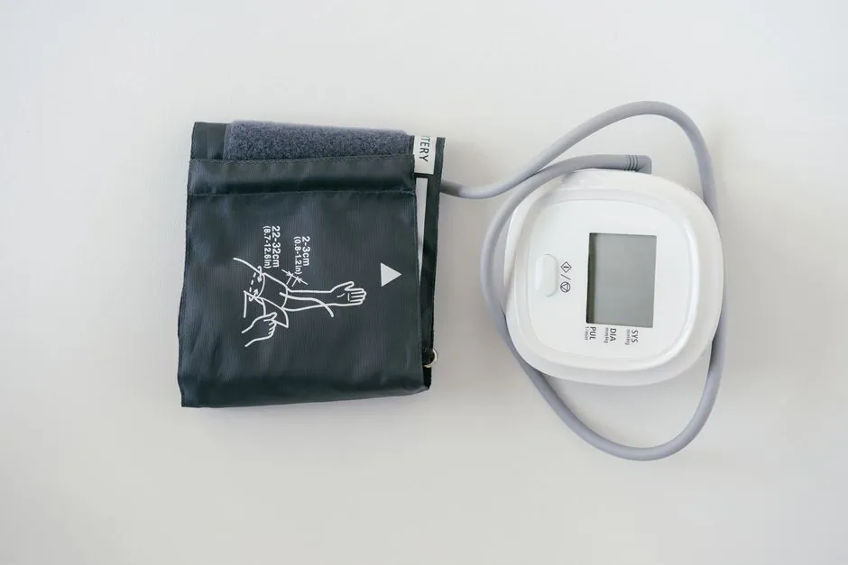
Pressure sensor total error band is the better installation-performance specification because it includes the static error band, thermal effects, and adjustable errors rather than laboratory accuracy alone [S1][S2].
The comparison matters across the selected pressure range, compensated temperature range, linearity method, zero and span adjustments, and application error budget.
Why the Two Accuracy Figures Are Not Equivalent
Simple accuracy describes potential measurement performance under thermally stable, laboratory-like conditions without external physical disturbances, while total error band is intended to represent performance when realistic environmental effects are present [S4]. A headline such as ±0.25% of full-scale output therefore does not establish the complete field uncertainty.
Accuracy commonly covers non-linearity, pressure hysteresis, and non-repeatability, with zero-point and span errors included by some manufacturers and listed separately by others [S1]. The total error band adds thermal effects and adjustable errors to the static error [S1].
For example, non-linearity of 0.25% FSO, hysteresis of 0.15% FSO, and non-repeatability of 0.10% FSO combine by root-sum-square to approximately 0.31%, compared with 0.50% for a direct arithmetic sum [S5]. This calculation is a static-error example, not a complete TEB unless thermal and adjustment terms are added.
What Total Error Band Includes
A pressure sensor total error band normally starts with a static error band and adds temperature-related zero and span shifts plus adjustable zero and span contributions over the compensated range [S1][S2]. The static error band is calculated as the root sum square of non-linearity, hysteresis, and repeatability [S4].
Linearity can be referenced to an end-point line, a best-fit line through zero, or a best-fit straight line, and each method produces a different result [S1]. Hysteresis is the output difference at the same pressure during rising and falling cycles, while repeatability describes consistency at identical conditions [S5].
For a pressure transmitter, inspection should confirm whether the published band includes zero and span errors, the temperature limits used for compensation, and whether the value is typical or maximum [S1]. A typical value is often less useful for acceptance than a stated maximum, because it leaves the distribution of individual units undefined [S1].
Decision Matrix: Accuracy or Total Error Band

Simple accuracy is adequate for laboratory screening, identical test conditions, or a preliminary comparison when temperature and adjustment errors are already excluded from the calculation. It is not adequate for a field acceptance limit that must remain valid across changing ambient conditions [S1][S4].
Total error band is the stronger choice for installed process measurement, qualified outdoor equipment, and applications with a defined compensated temperature range. It costs more to establish because the manufacturer must characterize thermal and adjustable errors, but it reduces the risk that a nominal accuracy figure will be mistaken for field performance [S2][S7].
The comparison across five decision criteria is straightforward. Cost and characterization effort are lower for simple accuracy; installation relevance is lower for simple accuracy; comparability improves when the linearity method, included terms, and temperature range are disclosed; and field-performance prediction is stronger with TEB. Resolution is not accuracy, so a high-resolution output does not reduce either error specification [S5].
Use Cases and Selection Boundaries
Total error band is appropriate when pressure sensors are installed where ambient temperature varies, zero and span adjustments contribute to uncertainty, or a control system needs a defensible maximum error limit. It is also valuable for pressure transmitters used in test, measurement, product development, and digitally compensated aerospace applications [S4].
Simple accuracy can be sufficient for bench comparison, screening incoming units, or a project with a tightly controlled environment and a documented calibration procedure. It becomes inadequate when pulsation, vibration, mounting stress, electromagnetic interference, or temperature cycling can change the result [S5].
For pneumatic and hydraulic installations, the error requirement should be tied to circuit function rather than selected from the most favorable datasheet headline. A companion comparison of pressure sensor examples for pneumatic and hydraulic circuits shows why media, mounting, pressure range, and operating conditions must be considered together.
Limitations, Test Conditions, and Installation Error
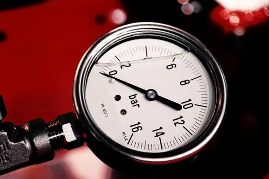
A TEB does not remove installation error. Mounting stress can bias a strain-based sensor, while pulsation, vibration, and electromagnetic interference can add noise or measurement uncertainty outside the datasheet error band [S5]. Pressure pulsation, vibration, and EMI add noise and error [S5].
Accuracy is not uniformly distributed across the full pressure span, and temperature coefficients can shift zero and span [S5]. The applicable pressure range, compensated temperature range, reference conditions, linearity method, and adjustment status must therefore remain attached to every comparison.
ISA-S37.1-1975 advises limiting the term accuracy to generalized descriptions and preferring error for specific performance specifications [S4]. IEC 61298-2 provides definitions for accuracy-related terms including non-linearity, pressure hysteresis, and non-repeatability, but manufacturer practice can still differ over whether adjustable errors are included [S1].
How to Verify a Supplier Datasheet
Request the full error budget, not only the headline accuracy. Confirm that the specification identifies non-linearity, hysteresis, repeatability, zero and span errors, thermal coefficients, compensation range, and the combination method [S1][S5].
Then convert the limits into engineering units for the application. A pressure range of 0–10 bar with a stated band in percent of full-scale output produces a fixed error magnitude across that range, while a percent-of-reading specification changes with pressure. Confirm whether the supplier uses FSO, percent of reading, or another basis before comparing products.
Verification should also include pressure cycling, temperature exposure, and installation checks. A pressure calibrator or deadweight tester can establish the as-found behavior against a traceable reference, but routine calibration does not expand the manufacturer’s stated TEB.
For procurement, the practical acceptance rule is to compare sensors with the same pressure range, compensated temperature range, linearity method, error terms, and adjustment conditions. Track whether each manufacturer supplies maximum accuracy, typical accuracy, static error band, or a complete total error band, because those labels are not interchangeable [S1][S7].