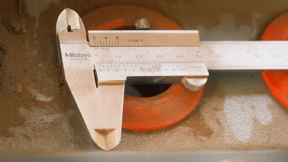
Ring-style inductive proximity sensors detect ferrous and non-ferrous metal parts as they fall through a circular sensing bore, with commercial 12mm units delivering response under 1ms, switching frequency up to 300Hz, and 6-36V supply range for direct PLC integration [S2].
The construction pairs an inductive coil that excites a magnetic field inside the bore with detection electronics; when a metal part passes through, eddy-current loading changes the field and triggers an output pulse, which is the same operating principle as a standard inductive proximity sensor but wrapped around a tube rather than placed at a flat face [S3].
Operating principle: static vs dynamic for falling parts
Ring sensors split into two operating modes that engineers select by application, not by hardware alone. Static sensors generate an output as long as metal is present in the detection zone and are used for level monitoring, jam detection, and wire-break verification [S1].
Dynamic sensors only fire on a passing part and are tuned for small, low-mass, fast-moving targets, with adjustable output pulse widths from 0.1ms to 150ms to guarantee the PLC sees a long enough edge and adjustable resolution that stays stable even when metal swarf contaminates the inside of the feed tube [S1][S5]. For falling-parts counting, dynamic is the default; static is the fallback for jam and no-part-present checks [S1].
Sizing the bore to the part
Ring bore diameters typically range from 10.1mm up to 15.1mm on Micro DC units with PNP or NPN, normally-open or normally-closed outputs, so the part must pass cleanly through the bore with a few millimetres of clearance to avoid shingling or wedging [S5].
A 10mm through-hole ring sensor is the common off-the-shelf choice for M3-M4 screws and small washers, while a 12mm or 15mm bore is specified for M5-M6 fasteners, springs, and small nuts; oversized bores reduce sensitivity to small parts, undersized bores cause mechanical jams upstream of the sensor [S6][S7]. Even steel balls with 0.6mm diameter can be detected through a properly sized ring sensor, which sets a practical lower bound on target size for high-resolution dynamic models [S5].
Speed, response, and signal conditioning

Detection speeds reach up to 35m/s on OEM ring-sensor families, well above gravity free-fall of small fasteners from typical feeder hoppers, so the part, not the sensor, is rarely the speed limit [S1].
Switching frequencies of 300Hz on 12mm NPN IP66 units correspond to a minimum pulse spacing of about 3.3ms, which at free-fall under gravity inside a 2m vertical tube limits the practical part rate to a few hundred parts per second per sensor; for higher throughput, multi-lane feeding with one ring per lane is preferred over faster electronics [S2][S4]. On the output side, IO-Link lets the integrator reconfigure pulse-stretching, electrical design (PNP/NPN), output function (NO/NC), and pull piece-counting and diagnostic data directly into the PLC [S1].
Ring inductive sensors beat ultrasonic and infrared through-beam sensors for small metal targets in transparent or non-metallic tubing: an HC-SR04 ultrasonic module and a generic IR reflection module both fail on 0.5cm-class parts, while a properly sized ring sensor sees steel balls down to 0.6mm [S2][S4][S5].
For a 12cm bore use case with single-part drop and immediate removal downstream, ring sensors also avoid the cost and processing load of camera-based counting, which scales linearly with lane count and pins one camera per PLC-class processor [S4]. The main limitation is material selectivity: only metals with sufficient conductivity and permeability (steel, stainless, brass, copper, aluminium above a size threshold) trip the output, so plastic pellets, wood, or ceramic beads require a different technology such as capacitive ring sensing or a fibre-optic through-beam [S3].
Wiring, protection, and environmental limits
Standard ring sensors run on 6-36V DC with NPN or PNP open-collector outputs, drawing the same three-wire or four-wire hookup as a standard proximity probe on a discrete input card [S2].
Sealed versions ship at IP66 with a brass nickel-plated flame-retardant housing and an operating window of -25°C to 65°C, which covers most indoor assembly cells and outdoor feeder cabinets but excludes sub-freezer conveyor lines and high-temperature washdown zones above 80°C [S2]. An onboard LED gives a per-part visual indication, and a potentiometer trims sensitivity on the device or, on IO-Link models, remotely through the master [S1][S2].
Typical applications in assembly and material flow
Three workloads dominate. Automatic feed screwing: the ring sits on the feed tube just before the driver and confirms a screw is present before the tightening cycle starts, so an empty cycle never advances [S1]. Automatic feed riveting: the ring verifies a rivet reached the setting position before the rivet stroke fires [S1].
Batch counting and wire-break detection round out the spec sheet, with wire-break on a moving spool being a long-standing static-mode use case for ring sensors mounted on the payoff [S1][S5]. For protocol-level integration of those same discrete counts, see how device-description files such as EDS vs GSD/GSDML sit between the IO-Link master and the controller when a ring sensor is one node in a larger remote-I/O block.
Track the following signals over the next procurement cycle: pricing on 12mm and 15mm bore IO-Link ring sensors from major European and Japanese suppliers, since the historical entry-level list price around $175 USD per unit for non-IO-Link ring sensors is the benchmark to beat for budget builds [S5]; and the release of higher-bore (20mm and above) ring variants for M8 and larger fastener automation, where current 10.1-15.1mm product lines cannot pass the part without re-machining the feed tube [S5].
For component-level specifications, see inductive sensor.