
A safety relay must be installed together with its contactors inside the same control cabinet per EN 60204-1 to prevent cross-circuits at the output, with stop category 0 implemented as immediate power removal to the machine or drive element [S3]. Ex-i variants such as the Phoenix Contact PSR-MC35 carry IECEx and ATEX certification for two intrinsically safe inputs up to zone 0 and installation in zone 2, on a 17.5 mm DIN-rail footprint [S4].
The qualified installer pool is restricted to electricians familiar with EN ISO 12100 and EN 60204-1 plus safety-literate application engineers [S3]; for Allen-Bradley Guardmaster and MSR safety relays, Rockwell Automation publishes dedicated CI and DI installation manuals plus an EtherNet/IP network interface installation document for field reference [S1]. Practical installation maps cleanly onto stop category 0/1 selection, channel count, and whether the signal generator sits in a hazardous area.
Stop Categories, Restart Logic, and Cross-Circuit Prevention
Stop category 0 is defined as immediate stop by removal of power, achieved by interrupting a machine or drive element according to EN 60204, while an automatic restart is permitted only if no hazardous situation exists, per EN ISO 12100 §6.3.3.2.5 [S3]. The Phoenix Contact application manual spells out the physical consequence: the safety relay and its downstream contactors share one installation space (typically the control cabinet) so that a cross-circuit at the relay's output cannot bypass the contactor's positive-opening contacts.
Engineers who confuse stop category 0 with stop category 1 introduce an unexpected controlled-stop delay that may not match the risk assessment; category 1 requires maintained power to the actuator for braking, then power removal at standstill, and is implemented with a separate timer or a dedicated safety timer relay. When the hazard analysis demands category 0 plus category 1 on the same machine, dual-channel monitoring with cross-fault detection at the relay is the conventional fix, not a single-channel wiring retrofit.
Channel Architecture: Single-Channel, Dual-Channel, and Cross-Fault Detection
Dual-channel safety relays from the Phoenix Contact PSR family monitor two redundant input paths and detect a single-channel short to the other channel via internal short-circuit monitoring on the input loop, which is the design intent behind the 17.5 mm housing and the forcibly-guided contact blocks [S3]. Single-channel wiring is acceptable only for low-risk applications where the input device itself is rated to the same Performance Level (PL) as the overall safety function; for PL d and PL e per EN ISO 13849-1, dual-channel with cross-fault detection is the de facto baseline.
Allen-Bradley Guardmaster and MSR relays ship in CI (single-wire, dual-channel with input redundancy) and DI (dual-input, dual-channel) wiring variants, and the Guardmaster EtherNet/IP network interface module extends the same safety protocol to a higher-level controller without losing the SIL/PL rating [S1]. Engineers retrofitting legacy single-channel e-stops should size the new safety relay to a minimum of two NO contacts and one NC contact on the input device so the diagnostic coverage reaches the 60-99 % band typically required for PL d.
Hazardous-Area Installation: Ex-i Inputs, Zone 0/2 Split
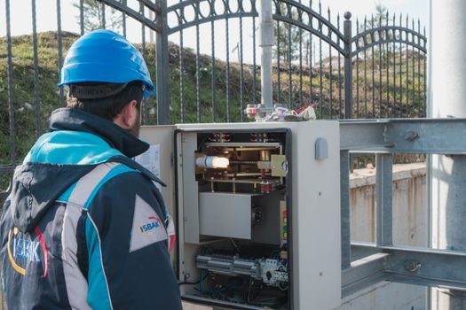
The PSR-MC35 Ex i safety relay has intrinsically safe input contacts certified to IECEx and ATEX, with two inputs that can be wired into zone 0 while the relay itself is installed in zone 2, on a 17.5 mm overall width [S4]. The zone 0/2 split lets a single non-explosive-proof enclosure hold the logic while the field device (e.g., a level switch inside a solvent tank) lives in the gas atmosphere, removing the need for a heavier-duty Ex d enclosure on the relay side.
Common field-generator pairings on PSR-MC35 include emergency switching off switches and safety door switches in single- or two-channel mode; the relay can be configured for automatic or monitored manual reset, which directly maps to the EN ISO 12100 restart rule above [S4]. Wiring in zone 0 must respect the Ex-i entity parameters (Ui, Ii, Pi, Ci, Li) on the relay's certificate, and the cable's distributed capacitance and inductance must be counted against those limits — exceeding them invalidates the intrinsically safe assumption even with the right model number.
Comparison: PSR-MC35 Ex-i vs Guardmaster/MSR CI vs Guardmaster/MSR DI
Three families cover the bulk of 2026 industrial panel builds; the table below lines them up against the four decision points that drive model selection on the shop floor. [S3]
Ex area coverage: PSR-MC35 reaches zone 0 inputs with IECEx + ATEX certification; Guardmaster and MSR families are non-Ex by default and require an Ex-rated remote input device or a barriers-based interface [S4][S1]. Footprint: PSR-MC35 occupies 17.5 mm on the DIN rail, comparable to the Guardmaster CI/DI single-width housing, so all three fit the same panel cut-out. Field-bus integration: only the Guardmaster line with the EtherNet/IP network interface publishes a safety-rated CIP-Safety path; PSR-MC35 is a pure hard-wired relay with no on-board bus [S1][S4]. Wiring pattern: CI = single-wire input with two channels and internal short-circuit monitoring; DI = dual-input, two separate channels brought back from the field; PSR-MC35 supports both single- and two-channel generators on its intrinsically safe inputs.
For a non-hazardous cell with a single e-stop and a safety door, the Guardmaster CI is usually the cheapest path; for a hazardous cell with door + E-stop in zone 0, the PSR-MC35 (or a Guardmaster + safety barrier combo) is the correct architecture.
Mechanical Mounting, Cabinet Layout, and Wiring Practice

DIN-rail mounting on a 35 mm top-hat rail is the universal fitment across PSR, Guardmaster, and MSR relays, with a recommended clip-to-rail torque of roughly 0.8-1.0 N·m and a derating curve that starts at ambient temperatures above 45 °C for some PSR models.
Screw-terminal torque on Phoenix Contact PSR terminals is typically 0.5-0.6 N·m for the 17.5 mm models, and the push-in variants ship with a release tool for stranded conductors. For a 17.5 mm-wide relay, label space on the front face is limited; engineers building more than ten cabinets should adopt a consistent marking convention (channel A / channel B / reset / output 13-14 / output 23-24) so that a fault on output 23-24 maps to a specific contactor coil within seconds, not minutes.
Acceptance Test, Proof Test, and Failure Modes
Acceptance testing on a new safety relay is a documented per-channel function test: force each input channel low, confirm the output contacts open within the manufacturer's response time (typically 10-25 ms for electromechanical PSR-class relays), and verify the diagnostic LED pattern matches the datasheet. For SIL 2 / PL d systems, proof-test intervals of 12 months are common; for SIL 3 / PL e, the interval often drops to 3-6 months because the dangerous undetected failure rate budget demands higher coverage, and each proof test should record the response time measured against the datasheet figure [S3].
Failure modes that should trigger replacement rather than repair include welded output contacts (visible as a closed circuit on a de-energized relay), input channel cross-fault that does not clear after a power cycle, and any case of relay chatter on a stable input signal. A safety relay is a one-shot protective device; the safety relay page in our reference encyclopedia documents the full obsolescence criteria and the typical 20-year mechanical service life used by Phoenix Contact and Allen-Bradley for parts planning.
Integration with Curtains, Fences, and Door Switches

Safety light curtains interface to a safety relay through OSSD (Output Signal Switching Device) outputs, and the relay's EDM (External Device Monitoring) input must loop back one normally closed contact from each downstream contactor to confirm dropout. A safety light curtain is a separate PPE-adjacent product and does not directly substitute for a relay; the relay is the logic device that turns the curtain's OSSDs into a category 0/1 stop and a lock-out for the guarded zone. Physical safety fence interlocks route through a door switch wired to the relay's two input channels, and the same enclosure practices (door switch + relay + contactor) apply; cross-fault detection and monitored reset become the audit-relevant design points. [S4]
Engineers specifying a safety relay in a robotic cell should verify that the relay's output contact rating (typically 6 A at 250 V AC) exceeds the inrush current of the contactor coil by at least 1.5×, otherwise the relay's electrical endurance spec will fall short of the mechanical endurance of the contactor. A short cross-reference to linear motion guidance is rarely needed here, but for cells combining a safety-rated linear axis with a relay-driven stop, a crossed roller guide audit should confirm that the axis' holding-brake circuit is also de-energized by the same relay output, otherwise the axis can drift after the stop.
For a 2026 panel build, the most reliable sourcing path is to lock in Phoenix Contact PSR or Allen-Bradley Guardmaster/MSR with the matching EtherNet/IP interface module, add a documented acceptance test report, and a structured proof-test log keyed to the SIL/PL target. Trackable signals for the next planning cycle: confirmation of the IEC 62061 / EN ISO 13849-1 datasheet numbers on the exact model, and verification that the cabinet layout keeps the relay and contactors inside the same enclosure to satisfy the cross-circuit rule from the Phoenix Contact application manual [S3][S1].
For related coverage, see Induction Furnace Installation: A Spec-First Field Guide for 2026.