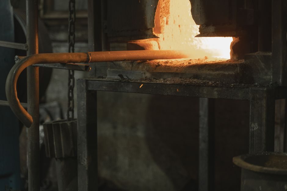
A coreless induction furnace is a refractory-lined crucible wrapped by a water-cooled copper coil, and installation acceptance fails unless the coil, the lining, the cooling loop, and the capacitor bank are all qualified before the first cold charge [S3].
Luoyang Ruixinsheng Industrial Technology supplies induction melting, holding, and heating equipment built for metallurgy, metal recycling, and processing plants, with the Continuous Casting Direct Rolling (CCDR) line — crucible → caster → soaking furnace → hot rolling — as one of the packaged integration paths buyers in 2026 still ask for [S1]. At the component level, Henan-based OEM/ODM shops list induction furnace, melting furnace, rolling mill, and closed cooling tower as a bundled delivery for foundries sourcing turnkey cells [S2].
Refractory Lining: The First Acceptance Gate
A coreless induction furnace uses a ceramic crucible as the secondary winding of an air-core transformer, so the lining is electrically and thermally load-bearing — not a consumable [S3]. Installation acceptance requires a sintered, crack-free lining dimensioned to the rated capacity; pour the first charge only after the documented dry-out and sinter schedule completes, otherwise the lining will crack on first heat-up and the coil will see molten metal.
Lining life is the single biggest maintenance cost driver on this equipment class, and the Melting Furnace TCO map walks the cost lines a spec engineer has to budget before signing a PO. Lining thickness, ramming procedure, and base-coat chemistry are OEM-specific — do not copy generic handbooks here; pull the OEM's installation drawing.
Coil, Cooling Water, and Skin-Effect Sizing
The primary winding on a coreless furnace is not copper wire but hollow copper tube, water-cooled internally to dump the I²R loss that the skin effect inflates at high frequency [S3]. Eddy power scales as P_e ∝ B²·f², so frequency selection drives both crucible coupling and copper loss — pick frequency as a coupled decision with coil cross-section, not in isolation.
For a typical medium-frequency installation — three-phase mains → rectifier → DC link → inverter → adjustable current into the capacitor-and-coil tank [S4] — the cooling skid, the rectifier, and the furnace body must be on a common grounded plan; water conductivity, inlet temperature, and ΔT across the coil should be logged from day one. A blocked or under-flowing tube will cook through long before the operator sees a temperature trip.
Power Factor Correction: The Capacitor Bank Is Not Optional
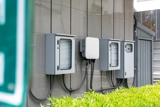
The magnetic coupling between primary and secondary in a coreless furnace is weak, so the native power factor sits between 0.1 and 0.3, and a static capacitor bank wired in parallel with the coil tank is mandatory equipment — not a power-quality add-on [S3]. During a heat cycle the power factor drifts, so the bank has to be switchable in steps to keep the bus close to unity through melt, hold, and pour.
Medium-frequency drives improve on this by using the DC link as a buffer, but the furnace-side capacitor bank is still required and its step-switching contactors are a common failure point [S4]. Acceptance test: record power factor at cold charge, mid-melt, and just before pour; if the spread exceeds the OEM tolerance, the bank needs re-staging before production handover.
Installation Options Compared: Coreless vs Channel vs Medium-Frequency
The coreless (high-frequency) build is the most flexible and the easiest to tilt for pour, but it pays the power-factor and copper-loss penalties above [S3]. Channel-type (core) furnaces give a much better power factor and lower electrical loss, but they cannot be drained fully and they constrain alloy changes — a different problem class, and the practical coreless-vs-channel trade is covered in the broader induction furnace reference.
Medium-frequency coreless units fed through a rectifier-inverter stack are now the dominant configuration for steel and large iron melts, with adjustable current and frequency giving the operator a tuning knob for charge mix and crucible size [S4]. Holding and pouring duty points to a separate holding furnace downstream of melt; do not try to use a melter on long hold cycles — refractory cost goes up and throughput goes down.
Who Induction Furnace Installation Is — and Is Not — For
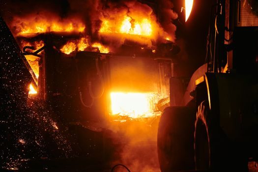
Spec-first induction furnace buyers in 2026 are typically mid-size foundries (5-50 t melt), steel minimills running CCDR lines, and non-ferrous shops in bronze, brass, and copper where coreless units are widely used [S1][S3]. A working crucible furnace background helps because the refractory-handling discipline transfers directly.
This is not the right path for ultra-high-volume iron production where a cupola furnace still wins on energy cost per ton, nor for tonnage shops that need continuous feed — those are different process lines, different refractories, and a different electrical budget. Buyers who only need a few kg per shift for jewelry or lab work should look at small vacuum or graphite-resistor units, not a 1 t+ coreless line.
Pre-Power Commissioning Checklist
Before closing the breaker on a new coreless installation, the spec engineer should walk at minimum: (1) lining sinter log and dimensional record against OEM drawing; (2) coil megger and hipot values recorded with cooling water off, then on; (3) cooling skid flow, ΔT, and conductivity logged under no-load pump run; (4) capacitor bank step test, each step logged for kVAR and bus power factor; (5) emergency tilt, water-loss trip, and earth-fault trip each tested with a written pass/fail [S3].
Then a cold charge, then a half-melt, then a full production heat — each gated on the previous. Skipping straight to a full heat is the most common way a new lining fails, and the cost of that mistake lands on the buyer, not the installer.
Failure Modes and When to Replace, Not Repair
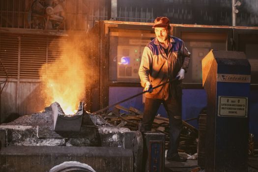
Three failure modes dominate the first year: (a) lining penetration — a hot spot on the coil outer surface means the refractory is gone, and the furnace must be relined, not run; (b) coil tube leak — pinhole leaks from cooling water quality escalate fast, and the OEM-specified water resistivity must be held or tube life drops to months; (c) capacitor contactor welding — single-step failure of the power-factor bank will drag the bus off unity and trip the drive, and a contactor that has welded once should be replaced, not re-used [S3].
When a fault takes out the coil itself — not the tube but the copper section — repair is rarely economic on a production furnace. The replacement decision point is the same one used in any melting furnace TCO model: when repair cost passes 50-60% of a new cold-side assembly, the call is replace. Track coil hour count, water quality log, and lining campaign count; that is the dataset a serious spec engineer hands to the next shift.
Next signal to watch: the 2026 Ekaterinburg EXPO metallurgy pavilion (Booth 2С42, Hall 2, 17-20 March) where Luoyang Ruixinsheng and similar Henan OEMs were scheduled to present CCDR and induction melting packages — a useful benchmark for what 2026-vintage equipment and integration scope Chinese lines are shipping into the CIS and EU markets [S1].