
Sectorial phased array scanning can electronically sweep a selected angular range with one element group, while linear scanning advances the probe along the inspection line and sequences focal laws at a fixed angle [S3][S1].
Both modes use multi-element probes, electronic delay laws and encoded position data, but they answer different inspection questions: linear mode maps a strip or welds systematically, whereas sectorial mode produces an angular cross-section for access-constrained parts [S1][S3][S4].
Operating Principle and Scope
Phased array UT uses multiple individually wired elements, electronic time delays, and constructive and destructive interference to steer, sweep and focus ultrasound [S3].
In a linear scan, the probe moves mechanically along the weld or region of interest while focal laws are sequenced with a fixed inspection angle [S1][S6]. A one-line scan is a single mechanical pass parallel to the weld, with encoder position tying each acquisition point to its physical location [S6].
In a sectorial scan, the active aperture remains fixed and the beam is electronically steered through an angular range [S1]. ASNT identifies beam steering, also called sectorial or azimuthal scanning, as a way to optimize detection probability by applying multiple appropriate angles [S3].
Decision Criteria by Scan Mode
The main decision criterion is geometry: choose sectorial when angular coverage or restricted access matters, and choose linear when repeatable coverage along a line, weld, panel, or bond line is the priority [S3][S4].
For cost and setup effort, both modes can use the same array instrument and probe family, so the decisive difference is software, focal-law programming, scanning fixture and data interpretation rather than a separate detector class [S3][S4].
Coverage, Resolution and Defect Characterization

Sectorial mode covers multiple angular responses from one aperture, and applying multiple appropriate angles can optimize detection probability [S3]. Focusing can optimize beam shape and size at an expected discontinuity depth, while phased array beams can be electronically steered, scanned, swept, and focused [S3].
PAUT can provide greater inspection coverage and efficiency than conventional UT for large or layered aerospace parts [S2]. PAUT is described as the preferred method for modern aerospace applications involving composite panels, bonded structures, and complex assemblies, while conventional UT relies heavily on operator interpretation of the A-scan [S2].
The imaging hierarchy differs by purpose. An A-scan plots echo amplitude against transit time; a B-scan presents depth against scan position; and a C-scan maps gated amplitude or depth over the component surface [S1]. Sectorial imaging adds the beam angle dimension, while linear imaging adds controlled position and, where programmed, focal-law coverage along that position [S1][S4].
Probe, Focal Law and Encoder Configuration
Industrial phased-array probes commonly contain 16–256 elements, although the active group may be much smaller than the physical array [S5]. The programmed angle, focal distance, wedge characteristics, material properties and scan pattern determine the delay law [S3][S5].
That example demonstrates why encoder indexing and the focal-law sequence must be treated as separate acquisition coordinates.
A linear encoder records each data point against a user-defined scan pattern and index resolution, whether the probe is moved manually or by a programmable motor-driven scanner [S1]. For linear PAUT, encoder tracking provides position-referenced scanning that can be used with the fixed-angle focal-law sequence to define the displayed image [S1][S2].
Best-Fit Applications and Exclusions
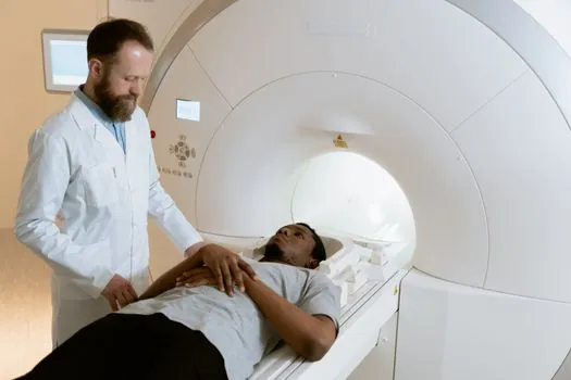
Choose sectorial PAUT for localized inspections requiring several shear angles, for components where probe access is restricted, and for orientation-sensitive features that may respond poorly at one fixed angle [S3][S4].
Choose linear PAUT for long welds, composite panels, stiffeners, sandwich structures and bonded joints where repeatable coverage along a path and position-referenced C-scan or B-scan documentation are required [S2]. Conventional UT is effective for thickness measurement, basic flaw detection, and lamination checks, while PAUT has become the preferred method for modern aerospace applications because it offers improvements in inspection quality and efficiency [S2].
Do not choose sectorial mode solely to obtain a cross-sectional display when the acceptance procedure requires dense sampling at one validated angle. Reliable scan positioning and position data are important in phased-array inspections, and conventional UT has limited scan coverage in large or layered parts [S1][S2].
Limitations, Failure Modes and Procurement Planning
Neither mode removes material-dependent inspection limits. Beam angle, focus, element count, wedge geometry and material sound velocity all affect sensitivity and defect sizing, and the focal-law calculator must use the actual probe, wedge, geometry and acoustic properties [S3][S5]. An image is not a substitute for a validated scan plan.
Operator interpretation remains lower with planned PAUT than with conventional A-scan-only UT, but sectorial images require correct angular interpretation and linear images require correct position tracking [S2]. Electronic scanning is typically an order of magnitude faster than a single-probe mechanical system, although mechanical movement remains necessary along the linear scan path [S3].
For instrument sizing, compare multi-element hardware and image-processing requirements before buying channels or TFM capability. A 16:64 instrument can support a 16-element active aperture on a 64-element probe, while a 32:128 instrument supports larger arrays and 32-element groups; the inspection plan, not the headline channel count, should set the requirement [S3][S5].
Standards, Records and Acceptance Basis
Specify the scan mode, angle range, focal depth, active aperture, probe frequency, wedge, scan speed, encoder resolution, image format, gate and defect-acceptance criterion in the inspection procedure. A sectorial plan should identify its reference angle and angular increment, while a linear plan should identify probe path, fixed angle, index spacing and focal-law sequence [S1][S3][S6].
Ultrasonic distance follows the governing relationship “Distance = velocity x time,” so the approved sound velocity and time-zero treatment must be fixed in the procedure [S1]. A phased-array C-scan collects gated signal amplitude or depth while the probe moves along one axis and the beam scans electronically along the other, using the programmed aperture [S1].
The final acceptance document should retain the calibration blocks, probe and wedge identification, focal-law file version, encoder calibration, image record and operator qualification. This creates an auditable link between the displayed result and the selected acquisition coordinates without relying on an unrecorded beam direction or scan position [S1][S6].
Use a 5 MHz, 64-element linear probe with 16-element focal laws over 37 mm (1.5 in.) as a documented configuration point, then validate any proposed 32:128 system against the same coverage, angle, focus and defect-sizing requirements before approval [S1][S3].