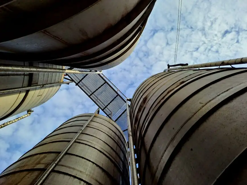
Seismic restraint systems for polyethylene tanks must be selected from tank size, stored-fluid weight, geographic location, anchorage, and foundation conditions, with project-specific engineering needed for non-standard installations [S1][S3].
Heavy-gauge steel brackets and adjustable tensioning assemblies can limit tank displacement, while cable restraint systems require adequate edge distance, concrete thickness, and anchor embedment to prevent overturning or lateral movement [S2][S3].
Define the Load Case Before Selecting Hardware
A restraint design starts with the stored load rather than the empty vessel mass. For a polyethylene tank, the seismic and wind cable system is based on tank size, fluid weight, and the tank’s geographical location [S3]. That combination matters because the same shell can behave differently when empty, partly filled, or operating near its full capacity.
The engineering objective is to keep the vessel from overturning, sliding, or moving far enough to damage connected piping and equipment. Anchor base plates and cable clips confine the tank during an earthquake, while the tank itself must maintain structural integrity and remain connected to its base under lateral and vertical seismic forces [S2][S3].
Restraint design is not limited to earthquake loading. Poly Processing groups seismic and wind restraints for chemical tanks because wind can create a separate overturning or sliding demand in exposed sites [S1]. A complete specification should therefore identify the governing site hazards rather than label the product “seismic restraint” and leave wind loading undefined.
Compare Restraint Architectures by Failure Mechanism
Cable restraint, post restraint, and rigid anchorage do not provide identical protection or installation requirements. The comparison below applies to the systems and design issues described for polyethylene vessels; it does not replace project-specific calculations for silos or other storage equipment. [S4]
Peabody’s engineering study found conventional cable-and-post systems used by the polyethylene tank industry to be ineffective and unsafe, and developed alternative designs intended to restrain plastic tanks without damaging them [S4]. That finding makes the restraint architecture a structural decision, not a generic accessory selection.
Use the Foundation as Part of the Restraint System
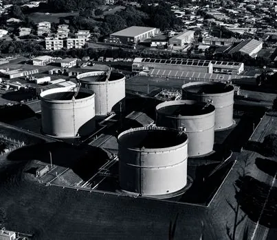
Concrete-pad thickness must exceed both anchor-bolt embedment depth and the diameter required to maintain minimum edge distance from the tank wall to the pad edge [S3]. This dimensional relationship is more informative than a generic statement that the tank needs a concrete pad: the pad has to be designed around the fastener geometry and the required crack-out distance.
A documented EQR Seismic Restraints 250 installation guide specifies three anchor bolts for tanks from 3,000 to 12,000 gallons and calls for a concrete slab with minimum 5,000 psi compressive strength [S5]. Those figures belong to that named guide and capacity range, not to every tank system, so they should not be transferred to silos or unverified capacities without project review.
The tank, fluid contents, restraint hardware, anchors, pad, and nearby piping must be treated as one load path. A restraint may work as a cable assembly but still fail through anchor pullout, pad edge breakout, shell deformation at a lug, or an unaddressed pipe connection. Snyder states that readers should contact its Industrial Products Division for questions or additional details and refers to Snyder's Guidelines for Use and Installation [S3].
Match Materials and Connections to the Installation
Galvanized steel is the standard restraint material identified by Snyder, with 304 stainless steel and 316 stainless steel offered as options [S3]. This selection affects corrosion exposure, not seismic capacity by itself, and the project still needs a site-specific assessment of the pad, anchors, tank shell, fluid contents, and restraint geometry.
Cable systems require molded-in tie-down lugs; tanks without those lugs require a manufacturer-supported alternative rather than an improvised field attachment [S3].
Three technical checks should remain visible in the submittal: connection suitability for the tank shell, load transfer into the supporting structure, and compatibility with nearby process connections. The research does not establish a universal allowable load for any cable diameter, bracket, lug, anchor, or tank size, so catalog dimensions alone are not an adequate engineering basis.
Apply Code and Risk Controls by Installation
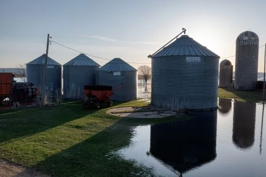
Snyder bases its anchor base plates and cable clips on the International Building Code and California Building Code [S3]. Rhino also identifies IBC, CBC, and ASCE 7 as governing references for water-tank restraint, with lateral and vertical seismic loads included in the design basis [S2]. The applicable code and local amendments must be confirmed for the installation address and tank use.
A partially filled tank adds liquid mass but can also introduce a higher center of gravity, so fill level and stored-fluid weight belong in the load case rather than being treated as a constant factor.
For critical water service, restraint failures can interrupt emergency supply and create liability exposure [S2]. For chemical service, the same movement can release stored material through damaged connections, making compatibility with the fluid and polyethylene tank material part of the equipment package. The engineering review should also distinguish seismic restraint from containment, which performs a different function.
Specify the Complete Delivered System
A procurement specification should identify the tank capacity and geometry, stored-fluid weight and density, geographic location, governing seismic and wind conditions, foundation type, anchor material, cable or post arrangement, tank-lug details, and required installation documents [S1][S3]. Stating only the tank nominal capacity leaves too many load and foundation variables unresolved.
For cable restraints, require confirmation of tank lug compatibility, anchor-bolt embedment, minimum edge distance, pad thickness, and installation tension. Snyder identifies sections 8.1, 8.2, and 8.3 of its Guidelines for Use and Installation as the installation references for its seismic restraint system [S3].
Do not assume that a restraint assembly can compensate for weak concrete, damaged anchorage, an undersized slab, or a rigidly connected pipe that transfers unintended loads. Do not treat cable restraint as the default for every polyethylene vessel: the documented concern over ineffective cable-and-post arrangements means the selected system needs an engineering basis and a stated load path [S4].
The next procurement checkpoint is the project-specific calculation package tied to the actual tank capacity, stored-fluid weight, site location, foundation, and connection details; retain the approved restraint layout and installation requirements with the equipment submittal [S3].