
Compressor-panel assemblies commonly combine 1 pressure switch, 2 gauges, a 1/4-inch safety valve, a detachable bracket, and 2 G1/4 connections in one installation package [S1].
The switch controls compressor motor cycling, while the gauges provide local indication of upstream and downstream air pressure for setup, diagnosis, and panel operation [S2][S4].
What the Integrated Assembly Actually Controls
An air compressor pressure switch starts the motor when tank pressure reaches the lower cut-in setpoint and stops it when pressure reaches the upper cut-out setpoint [S7]. This makes the switch the automatic control element, rather than a passive indicator.
A local pressure gauge provides the operator with immediate feedback from the receiver or supply line. A sudden pressure drop shown on the gauge can indicate a leak or another system inefficiency, while visible over-pressure helps operators identify an abnormal condition before equipment damage develops [S4].
The distinction matters in panel work. The switch makes the start-stop decision, but the gauge confirms what the machinery is doing. A switched panel without visible indication forces troubleshooting through remote alarms or electrical measurements, which is slower and less useful at the panel [S2][S4].
Choose the Configuration by Panel Function
One listed assembly contains 1 pressure switch, 2 pressure gauges, 1 safety valve, 1 detachable bracket, and 2 G1/4 components, covering monitoring, automatic control, and panel mounting in a single package [S1].
A two-gauge manifold is better suited to a panel that must compare compressor inlet and outlet pressure. The two-gauge configuration permits real-time monitoring on both sides of the regulator and provides a visible basis for adjusting stable outlet delivery [S2].
The two-gauge option has the clearest advantage when upstream and downstream pressure must be compared. The one-gauge arrangement is simpler and easier to read, while the unloader-equipped design adds a specific function rather than simply another indication point.
Set Cut-In, Cut-Out, and Differential Deliberately

Replacement pressure switches are offered in multiple psi ranges and port styles, so the selected model must cover the compressor receiver's normal operating band rather than merely match the nominal tank pressure [S3].
A D24918 example is specified for 120/150 psi and includes an integrated unloader valve. The unloader relieves trapped air pressure when the compressor shuts down, reducing the load encountered during the next motor start [S5].
One operating detail deserves more attention than most panel builders give it: the gap between cut-in and cut-out is the pressure-switch differential. Too narrow a band can produce rapid cycling, while an excessive differential can create a visible pressure swing at the outlet. The mechanism and setpoint behavior are explained in How a snap-action pressure switch trips at its setpoint.
Match Threads, Electrical Capacity, and Relief Path
The featured G1/4 components and 1/4-inch safety-valve connection must be checked against the actual panel tubing and compressor outlet [S1]. Thread size alone does not establish compatibility because thread form, sealing method, and whether the port is internal or external also affect installation.
The D24918 pressure-switch assembly is shown with a 1/4-inch MPT pressure port, while the product range also includes equipment identified as a 120/150 psi switch with an integrated unloader [S5]. These details matter because an MPT connection and a G1/4 component use different thread standards.
Electrical selection must cover the compressor motor-control circuit, including the switch's contact arrangement, voltage, current rating, and whether the application requires a single-pole or double-pole mechanism. A mechanical pressure rating alone does not establish that the contacts can interrupt the control or motor-circuit load.
The panel also needs a protected relief route. A safety valve in the assembly is not permission to oversize it, omit it, or trap the discharge. A pressure switch limits when the compressor runs; it does not independently provide over-pressure relief.
Use the Right Instrument Class for the Duty
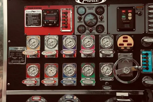
A general compressor panel requires a pressure switch, but breathing-air systems have a different instrumentation scope. Electrical pressure and temperature switches designed for breathing-air compressor systems are used to monitor their specific operating conditions [S6].
That distinction affects sourcing. A general panel assembly with 1 switch, 2 gauges, 1 safety valve, 1 bracket, and 2 G1/4 components should not be treated as a substitute for breathing-air-specific monitoring equipment [S1][S6].
For local indication, a conventional gauge supplies direct visual pressure information without an electrical signal. If the panel also needs a remote reading or process-control input, the instrumentation scope expands beyond the switch-and-gauge package, and a separate pressure transmitter may be required.
Do not use a pressure switch as though it were a transmitter. The switch provides discrete control at its setpoint, whereas a transmitter produces a proportional measurement signal for indication, recording, or process control.
Commission with Independent Pressure Evidence
Commission the switch by applying or monitoring known pressure at the setpoint transition, while comparing the switch state with the integral gauge indication. This verifies both the electrical action and the relationship between the sensing point and the displayed value. [S1]
Record the compressor-off pressure, the pressure at which the motor starts, and the pressure at which the motor stops. The three values expose an incorrect range, excessive differential, blocked or restricted gauge connection, and wiring or contact failure that a simple on/off test can miss.
Also verify that the panel remains readable at operating pressure, that the gauge faces the normal viewing position, and that the relief path cannot be isolated during normal maintenance. The snap-action contact pressure gauge comparison provides further context where a switching indication is being considered alongside ordinary mechanical indication.
A complete compressor-panel specification should list the switch range, cut-in and cut-out points, differential, port type, electrical rating, gauge range and accuracy class, safety-valve connection, mounting arrangement, and required relief routing. That converts a visually complete assembly into a panel that can be installed, tested, and maintained without guesswork.
