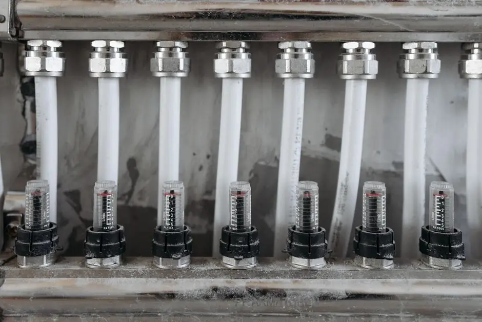
A snap-action pressure switch is a binary electromechanical device: it has no analog output, no 4-20 mA loop, and no firmware, yet it trips its electrical contacts at a calibrated setpoint using only process pressure as the energy source [S1][S4]. The trip is driven by a force balance between the pressure acting on a sensing element and an opposing range spring, with the contact transfer executed by a snap-action (microswitch) mechanism rather than by slow contact wipe [S1][S5].
This topology makes a mechanical pressure switch the only pressure switch variant that still trips when facility power drops, because the switch element itself draws no power, only the downstream alarm or shutdown circuit does [S4]. Engineers specifying a setpoint should think in terms of three numbers: the setpoint, the reset point, and the deadband (setpoint minus reset), which together define the switching window and the cycling behaviour of the contact [S6][S8].
Force balance: pressure versus the range spring
The trip starts with a force balance on the sensing element. NOSHOK's white paper gives the classic expression: Media Pressure × Diaphragm Area = Spring Constant × Spring Compression Length, so set pressure is a function of effective area, spring rate, and preload [S1]. High-pressure switches use small diaphragms or pistons with stiff springs; low-pressure switches use large diaphragms with soft springs, and any of the three parameters can be traded against the others to land a given setpoint [S1].
When applied pressure equals spring preload, the diaphragm or piston has travelled just far enough to begin driving a pushrod into the snap mechanism [S3][S7]. A few more psi of process pressure is enough to carry the snap spring past its over-centre point, at which point the stored mechanical energy in the snap spring releases and the contacts move in a single rapid stroke [S5][S7]. This is why a snap-action switch makes a sharp audible click and not a slow creep: the contacts cross from one state to the other in milliseconds, which minimises arcing and contact welding compared with a slow-make, slow-break design [S2][S5].
From diaphragm to contacts: the mechanical chain
The signal path inside a typical mechanical pressure switch is fixed: pressure chamber, sensing element (diaphragm, bourdon tube, or piston), pushrod or transfer lever, snap-action contact, and external terminals [S3][S7]. Firgelli's animated topology explicitly traces pressure chamber to diaphragm to pushrod to snap element to electrical contact, although the motion is prescribed and is not a calibrated displacement model [S3]. Semiconductor-for-You describes the same chain: once the diaphragm force exceeds spring tension, the diaphragm flexes, drives the pushrod upward, and trips the internal snap-action micro switch [S7].
On the sensing-element side, three families dominate. Diaphragms (often Hastelloy, Monel, or PTFE-coated stainless steel for corrosive service) cover low-pressure and chemically aggressive media; bourdon tubes suit high-pressure hydraulic work above roughly 10,000 psi; pistons take the abuse of dirty, spike-prone fluids but at the cost of higher actuation force [S2]. SOR's piston-style industrial switches use exactly this geometry, with process pressure compressing a calibrated range spring that drives the piston into a snap-action switching element at the set point [S4]. Sensing technology choice is independent of the snap mechanism, but it sets the available setpoint range, proof pressure, and media compatibility [S1][S2].
Setpoint, reset, and deadband: the three numbers that define the trip
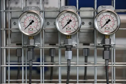
Every snap-action pressure switch is specified by three numbers, not one. The setpoint is the rising (or falling) pressure at which the contacts transfer; the reset point is the pressure on the opposite side of setpoint at which they return to their normal state; and the deadband, also called differential or reset differential, is the arithmetic difference between them [S6][S8]. Ashcroft states this directly: as pressure rises, the switch trips at its setpoint, and when pressure begins to fall it must move beyond the reset point before the switch changes state again [S8].
A worked example from AutomationDirect: a switch set to trip at 100 psi on rising pressure will reset at 90 psi on falling pressure, giving a 10 psi deadband, which is typical for general-purpose industrial switches [S6]. SucoeSi puts the typical range at 5–15% of setpoint, which is wide enough to prevent rapid on/off cycling around the trip point, a behaviour that would otherwise arc the contacts and wear pumps or compressors [S2]. Selecting too narrow a deadband invites chatter; selecting too wide a deadband costs process precision, so the differential number on the nameplate is a real engineering knob, not a footnote [S2][S6].
Mechanical versus electronic snap-action switches
The snap-action contact is the same physical part in both families, but the energy that drives it is different. A mechanical pressure switch gets its actuation energy directly from process pressure acting on the sensing element, so it needs no power supply, no transducer excitation, and no signal conditioning to trip [S1][S4]. An electronic pressure switch uses an internal pressure sensor (typically piezoresistive or SoS) to produce a voltage, then compares that voltage to a user-adjustable reference in hardware or software to drive a solid-state or relay output [S1].
For a fixed budget, mechanical units give coarser accuracy and larger deadband but absolute immunity to power loss; electronic units give tighter setpoint accuracy, adjustable deadband, and often 4-20 mA or switching output in the same package, but the trip function disappears the moment loop power is lost unless a UPS is in the chain [S1][S4]. A side-by-side decision reads roughly: choose mechanical for safety interlocks, fire pumps, and any trip that must work through a blackout; choose electronic where you need a precise, adjustable setpoint, on-board indication, or integration with a pressure transmitter network and the loop power can be guaranteed [S1][S4].
Why the snap geometry matters for contact life

Snap-action mechanisms are not used in pressure switches for feel, they are used to control contact velocity independent of how slowly process pressure is rising. E-Switch's description of generic snap-action switches is the same physics used inside a pressure switch: an external force compresses an internal spring until it passes a critical point, at which point the spring rapidly changes position and the movable contacts snap into a new state [S5]. The contact transfer is fast, the dwell at intermediate positions is near zero, and the audible click is a byproduct of that rapid mechanical transfer [S5].
The benefit is electrical: fast transfer means short arcing time, which means less contact erosion and less chance of the contacts welding shut under a heavy inductive load such as a motor contactor or solenoid valve [S2][S5]. Compared with a slow-make pressure switch, a snap-action unit typically delivers longer mechanical life, more consistent trip force across millions of cycles, and a clean break that is easy for a pressure gauge or test bench to read on the way up and on the way down [S2][S5]. That same snap geometry is also why the trip and reset points are separated by a fixed deadband rather than occurring at the same pressure, because the snap spring has to be reloaded past its over-centre position before it can fire again [S5][S6].
Selection criteria: matching the switch to the service
Four criteria drive most snap-action pressure switch selections: sensing element compatibility, setpoint range and adjustability, deadband, and electrical rating. Media compatibility is set by the wetted material, with 316L stainless steel as the default and Hastelloy, Monel, or PTFE coatings for corrosive chemicals [S2]. Setpoint range is set by the sensing element: diaphragm designs cover the low end (often below 100 psi), bourdon and piston designs cover the high end (up to and beyond 10,000 psi) [S2][S1]. Deadband is typically 5–15% of setpoint for general-purpose switches and can be much wider on fixed-deadband safety switches [S2][S6].
Electrical rating is the easiest place to get burned: a snap-action microswitch inside a pressure switch is commonly rated 5 A at 250 VAC resistive, but motor and solenoid loads derate the contact severely, and the rating on the switch nameplate (not the marketing brochure) is the only number that should be used for safety shutdowns [S2][S5]. For applications where the trip must work through power loss, the mechanical path described in SOR's 2026 article is the deciding factor, since the pressure measurement chain goes sensor, snap contact, terminals, and load with no powered instrument in between [S4]. For higher accuracy, adjustable deadband, and HART or IO-Link output, an electronic pressure switch is the better fit, with the trade-off that the trip function is no longer independent of facility power [S1][S4].
Failure modes and limits to respect

Three failure modes account for most snap-action pressure switch service calls: contact welding from inrush on inductive loads, setpoint drift from sensing-element fatigue or over-pressure, and leakage at the process connection. The first is controlled by derating the contact for the actual load, adding a snubber or interposing relay for motor and solenoid coils, and accepting that snap-action transfer, while fast, is not a substitute for arc suppression [S2][S5]. The second is controlled by selecting a switch with a proof pressure comfortably above the maximum expected spike, and by treating any large overpressure event as a reason to recalibrate or replace the unit [S1][S2].
The third is controlled at specification time by matching the process connection (NPT, BSPP, flanged) and the wetted material to the fluid, and by recognising that the snap mechanism itself does not care about the fluid, only the sensing element and seal do [S1][S2]. Beyond those, mechanical pressure switches are inherently coarse compared with a pressure sensor or pressure calibrator, and any application that needs better than roughly ±1–2% of setpoint accuracy should be looking at electronic or transmitter-based trips instead [S1]. Treat the snap-action switch as a binary safety device, not a measurement device, and it will outlast the more sophisticated electronics around it [S4].
Trackable signals: SOR's June 2026 guidance on mechanical switches as blackout-proof safety devices, and Firgelli's 2026 threshold explorer, which now reports only declared-threshold arithmetic and refuses to model actual trip behaviour, both reinforce that a snap-action pressure switch is a discrete component, not a measurement instrument, and should be specified on setpoint, reset, deadband, wetted material, and electrical rating in that order [S3][S4].
For related coverage, see Cold-Box Amine and Binder Cost per kg of Core: 2026 Breakdown.