
Angular contact ball bearings support combined radial and axial loads in machine tool spindles, and their axial-load capacity increases as the contact angle increases [S1][S4].
The bearing set for a spindle should be selected against operating speed, thrust direction, preload, lubrication, mounting arrangement, and allowable vibration, rather than by diameter alone [S3].
Vibration Grade Cannot Be Isolated From The Bearing Set
A spindle bearing grade is not meaningful unless it describes the complete system: bearing accuracy class, matched preload, contact angle, cage, lubrication, fit, and shaft or housing alignment. Angular contact bearings provide the geometry for stiffness, axial positioning, and low vibration, but their performance depends on correct installation and controlled preload [S1][S3].
These references provide the framework, but they do not make every catalogue bearing equivalent at the machine level.
The angular contact bearing grade should therefore be tied to measurable outcomes such as runout, vibration frequency content, preload repeatability, and temperature during a defined speed and load cycle.
Contact Angle Sets The Load And Speed Trade-Off
The contact angle is a key feature of angular contact bearings, and their axial-load capacity increases as the contact angle increases [S1]. A larger contact angle raises axial capacity and reduces the relative radial component, while a smaller angle favors radial capacity and higher-speed potential [S1][S5].
The engineering rule remains straightforward: higher angles suit heavier axial loads, while lower angles suit higher rotational speeds. For a spindle, select against the actual thrust cycle rather than the maximum catalogue axial capacity.
Matched Arrangements Change Stiffness And Alignment Tolerance
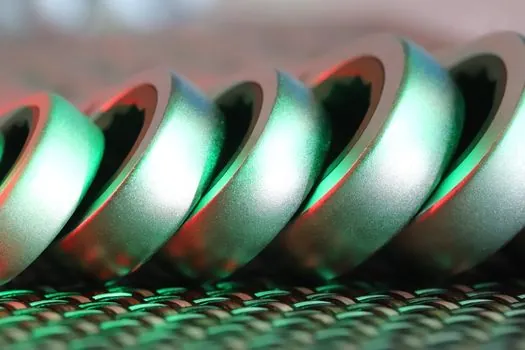
Back-to-back and face-to-face pairs both support radial loads and axial loads in either direction, but their load-center geometry differs. Back-to-back pairs provide a wider load-center separation, higher moment-load capacity, high rigidity, and lower allowable misalignment; face-to-face pairs use a shorter load-center distance and permit more misalignment [S1].
A tandem stack is appropriate when thrust acts in one direction only, while DB or DF is preferred for bidirectional axial restraint.
For the ABEC 7 and ISO P4 distinction, see Map ABEC 7 and ISO P4 for Angular Contact Bearings.
Preload Controls Vibration, Heat, And Life
Initial axial preload has a significant influence on the vibration level of a grinding-machine spindle, establishing preload as a controlled variable rather than an installation detail [S2]. Preload reduces internal clearance and rolling-element micro-movement, improving stiffness and supporting repeatable runout, but excessive preload raises friction, heat generation, and the risk of reduced bearing life [S3].
Three values need definition in a spindle bearing specification: the initial preload, the preload method, and the permitted variation after mounting. The mounted condition must be verified against the spindle builder’s target rather than the bearing catalogue alone [S3].
Cleaning, lubrication, cage selection, and housing fit can change vibration as much as the nominal bearing grade. High-speed spindle reliability depends on cleanliness and correct setup, not only bearing quality [S3]. A grease-lubricated spindle requires a lubricant and relubrication strategy compatible with the selected bearing and speed.
Compare Main Bearing Types Against Spindle Criteria
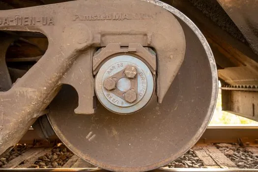
Angular contact ball bearings are suitable when the spindle must carry combined radial and axial thrust while maintaining stiffness and accurate axial positioning. Deep groove ball bearings have a 0° contact angle and are primarily radial-load bearings, while angular contact bearings are designed for both radial and axial loading [S5].
The comparison shows why a ball bearing is not interchangeable with an angular contact spindle set. Angular contact geometry provides the load path and stiffness needed where cutting forces create radial load, axial thrust, and dynamic excitation together [S3]. It is less suitable when the requirement is only lightweight radial support, or when axial loads, impact, contamination, or very low speed dominate the duty.
Specify And Test The Vibration Grade
A robust spindle specification should state the accuracy or vibration class, matched-set arrangement, contact angle, preload class and method, speed rating, lubrication method, cage type, fitting tolerances, and reference mounting condition.
One bearing-analysis approach mounts the test bearing on a quiet spindle and evaluates three frequency bands: 50–300 Hz, 300–1,800 Hz, and 1,800–10,000 Hz [S7]. At machine level, record spindle speed, preload, temperature, radial or axial load, and measurement location so that the result can be reproduced.
Do not accept a single no-load vibration figure as proof of machining performance. Test under representative cutting loads because preload changes vibration response and generated forces affect the operating system. Dynamic-stiffness analysis also depends on the contact behavior between the balls and the inner and outer raceways [S8], which is why bearing class alone cannot predict spindle behavior.
Apply Grade Controls To The Complete Spindle
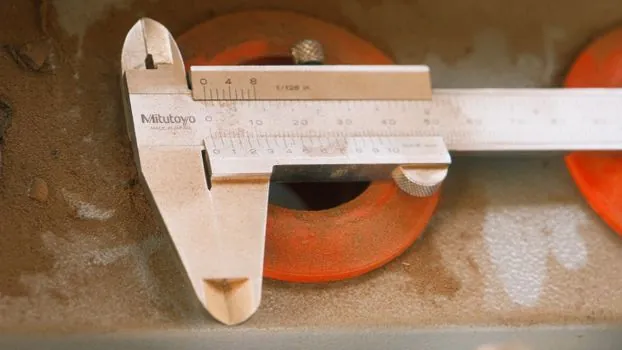
Use ISO 492 to define the bearing accuracy class and ISO 15242 for the vibration measurement framework, then add spindle-specific limits for preload, runout, temperature, and lubrication condition [S3]. For machining centers, grinding spindles, and precision motor assemblies, the bearing set should be selected to preserve stiffness, positional accuracy, and heat control at operating speed [S1][S3].
The most defensible purchasing decision is a matched, traceable bearing set with a stated grade and preload method, supported by a spindle-level test at the intended speed and load. The trackable signals are the measured vibration bands, runout variation, and temperature rise during a repeatable duty cycle.