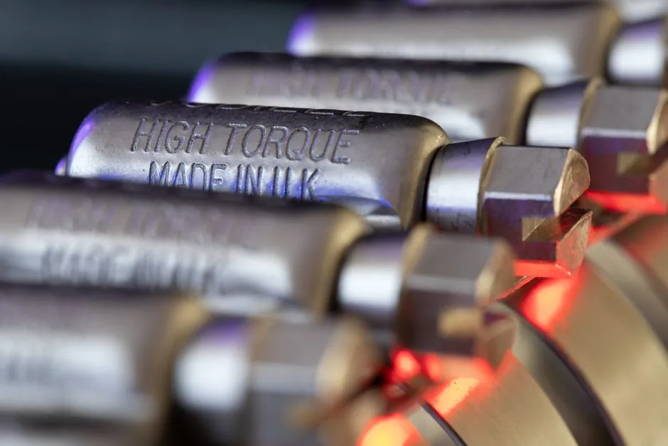
A capping machine should apply enough torque to compress the liner against the bottle finish without damaging threads, closures, or glass, but no universal setting works for every package combination [S1][S2].
Application torque and removal torque are separate controls: one sets the closure, while the other verifies whether seal retention remains within the package supplier’s approved range after material relaxation [S2].
Define Torque by Package and Closure
Capping torque is the rotational force used to drive a closure onto its container, commonly measured in inch-pounds or Newton-metres; this force compresses the liner and creates the seal [S2]. The bottle neck finish, closure geometry, cap material, liner material, and product compatibility must be fixed before selecting a machine or setting its torque range [S2][S4].
Chuck cappers suit high-precision torque control, spindle cappers are used for adaptable, faster production lines, and snap cappers are designed for press-on lids [S3]. A capping machine with independent head control reduces operator variation, but the control system cannot compensate for an unsuitable closure, contaminated thread, mismatched bottle finish, or worn spindle [S2][S3].
Application torque is not the same value as removal torque. Removal torque is commonly measured 24 hours after capping and normally falls to about 40–60% of the applied value because of gasket compression, material creep, and thermal relaxation [S2]. That ratio is a validation clue, not a universal factory setting.
Choose a Qualified Torque Window
A manufacturer-specific torque window should include minimum application torque, maximum application torque, and acceptable removal-torque limits; no supported package specification supplies one universal numerical window across all containers [S1][S3]. One published guideline uses 8.0–12.0 inch-pounds as an acceptable removal-torque range for its specified application [S6]. A separate example produced approximately 12.5 inch-pounds of removal torque when application torque was approximately 17 inch-pounds [S7].
Use those examples to understand measurement practice, not to transfer settings to another closure. Approximately 12.5 inch-pounds of removal torque is about 74% of approximately 17 inch-pounds of applied torque, which falls above the typical 40–60% relationship between stabilized removal torque and application torque and supports validating each package separately [S2][S7].
For an induction-sealed closure, application torque still affects the starting seal condition even though the induction process supplies the sealing energy. Enercon’s demonstration used identical containers and liners with the same sealer power level and conveyor speed, changing only cap torque, and described the recommended torque for its demonstration as half the cap size in inch-pounds [S5].
Set, Measure, and Correct Torque Drift
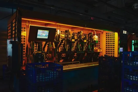
Start with the closure supplier’s application-torque range, confirm the bottle-finish match, and tune the capping head until consistently measured removal torque falls within the approved range [S1][S2][S6]. Measure on filled containers with the intended liner and product, apply the tool slowly and evenly, avoid reused closures, and keep the torque instrument calibrated [S2].
Record application torque, removal torque, cap diameter, closure lot, bottle-finish code, line speed, and measurement time for the validation run. Trend the results rather than relying on a single good container; chuck fit, dwell time, spindle pressure, spindle wear, clutch drift, thread contamination, temperature, and humidity can all shift measured torque or seal behavior [S2].
Distinguish machine settings from verification tools. The coding machine may support downstream traceability, but the capper setting itself must be confirmed by a calibrated torque meter and the closure’s removal test [S2]. The distinction prevents a correctly displayed machine value from being treated as proof of an acceptable seal.
Compare Torque-Control Approaches
Chuck capping provides direct control of applied rotational force and is suited to precise applications, while spindle capping offers versatility for high-speed lines but requires close attention to spindle fit and wear [S3]. Press-on or snap capping depends mainly on axial force and closure geometry, so rotational torque is less useful as the primary acceptance measurement for that format [S3].
The case packing machine may become the final downstream source of handling disturbance, so seal validation should reflect the route from capping to shipping. A torque setting that passes an immediate bench check but produces leaks after secondary handling has not established an adequate operating window [S2].
Use Failure Tests Beyond Torque Readings
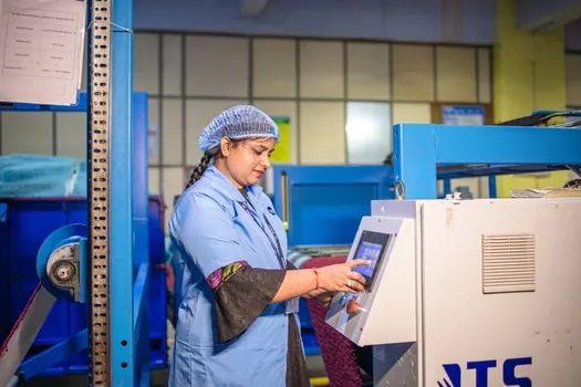
Under-tightening can produce a closure that appears seated while allowing progressive torque loss, leakage, contamination, or spoilage; over-tightening can crush liners, strip threads, deform finishes, damage fragile glass, or make the package difficult to open [S2][S3]. A torque reading alone therefore does not establish package integrity.
Validate representative filled packages through inversion, vacuum or pressure testing, and hot-fill cool-down cycling where those conditions apply [S2]. For induction seals, inspect the liner and seal area for the failed-versus-successful result patterns demonstrated under different application torques [S5]. Record defect rate by closure lot and machine head, because a pooled average can conceal one drifting head.
This approach is unsuitable for treating torque as the sole quality-control method for push-on closures without pressure data, or for declaring an induction seal acceptable without inspecting the bonded area. The governing acceptance criteria must come from the specific package and closure system.
Build a Repeatable Commissioning Procedure
A commissioning plan should define cap feeding, bottle guide control, spindle adjustment, torque setting, and handling of different cap diameters, with the required proposal covering those operating controls [S8]. The machine proposal should also identify the test method, acceptance limits, sample size, filled-container condition, and measurement interval [S2][S6].
Use the capping and sealing machines versus induction sealers distinction when defining the equipment scope: closure application and induction sealing are separate operations, although their results interact through cap torque and liner compression [S5].
After approval, recalibrate the torque tool, verify spindle and chuck condition, and repeat the application and removal checks after a closure-lot change, bottle-finish change, maintenance intervention, or documented drift. Track removal torque at the defined validation interval, production torque distribution, and seal-failure results, because a stable machine setting alone does not guarantee a stable package seal [S2][S6].