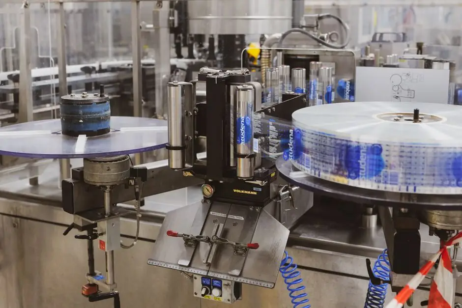
The gap must combine adequate clearance, a rigid mounting reference, sensor-based height setup, and nozzle-by-nozzle inspection to maintain repeatability across cartons [S4][S5][S7].
Standoff Controls the Printable Tolerance Window
Printhead standoff is the physical separation between the inkjet printhead and the coding surface.
A larger clearance does not automatically mean better quality. The effective standoff must remain stable while the substrate moves through the coding position, because variation in gap changes drop formation, character edges, and code legibility [S4].
The 2 mm setting specified for a Roland DG flatbed printer is a machine-specific setup value, not a universal target for carton coding [S3].
The coding machine specification should therefore identify the required clearance, sensing method, maximum substrate-height variation, and acceptance test for the coded result rather than list an isolated distance without its operating condition [S2][S4][S7].
Choose Clearance by Substrate and Machine Geometry
Flatbed printing has a different geometry. The manual for the Roland LEF2-300 instructs operators to set the distance from the highest point of the object to the lowest print surface at 2 mm [S3]. This value must be treated as equipment-specific and reconciled with the printer's head-gap sensor, manual height adjustment, and flat-table position.
A comparison of the main configurations is straightforward. Sensor-controlled positioning can reduce setup error, but it cannot correct a loose or deflecting mounting structure [S2][S3][S7].
Use Sensor Setup and a Fixed Mechanical Reference

The Roland DG LEF2-300 setup separates height adjustment from print-area settings and includes a head-gap sensor dedicated to detecting the object beneath the printheads [S3]. That architecture prevents a fixed gap from being treated as adequate when the substrate height changes.
For carton coding, direct-printing guidance identifies five relevant controls: guiding, printhead distance, stability, speed, and correct printhead mounting [S7]. The standoff should consequently be referenced to the final positioning hardware rather than to a moving belt, carton flap, or loosely supported guide.
Maintenance instructions divide the LEF2-300 adjustment sequence into manual height setting, automatic adjustment, and head-gap sensing [S3]. This three-part approach is a sound specification pattern: establish the mechanical height, detect the actual surface, and verify the final printhead relationship before production.
An UltiMaker gantry-height example uses 25 mm as a machine-specific dimension from the nozzle tip to the bottom of the X beam, showing why machine coordinates should not be confused with a printhead standoff specification [S6].
Verify Alignment, Jetting, and Character Quality
Nozzle-by-nozzle inspection assesses printhead health and alignment by scanning a printed coupon for missing jets, deviated lines, and other failures [S5]. That inspection verifies the hardware, while the standoff test verifies its installed relationship to the product.
Printhead manufacturing measurements provide three additional checks: drop volume, drop velocity, and missing-jet identification. The cited imaging platform resolves at 0.5 µm and uses an 8 million fps-equivalent exposure time, allowing drops, mist, and satellites smaller than 1 pL to be examined [S5].
Dot positioning adds a geometry-focused check for dot size, shape, and position accuracy. Frequency sweeping tests jet consistency across a list of firing frequencies so the waveform and operating speed can be assessed rather than assumed [S5].
On the finished package, acceptance should include character edge definition, code readability, alignment to its target position, and repeatability over the permitted carton-height range. Printhead condition, waveform tuning, and rigid printhead mounting remain relevant considerations alongside printhead distance [S5][S7].
Separate Gap Errors from Motion and Ink Problems
Blurred characters are not proof of an incorrect standoff. A loose mount, unstable guide, speed mismatch, waveform problem, missing nozzle, or ink-substrate mismatch can also degrade the mark [S4][S5][S7].
A standoff setting should be challenged through controlled steps: print a reference coupon on a calibrated surface, inspect all nozzles, then introduce the expected substrate-height variation. If quality changes with carton height, inspect sensor calibration and the final mounting reference. If the mark remains defective at a constant height, examine jetting, motion, ink, and substrate behavior instead of increasing clearance blindly.
The Time Code work on multifunctional 3D printheads demonstrates a separate synchronization issue: auxiliary controls must not interrupt the programmed print path when accuracy, precision, and speed are being optimized [S1]. Although additive manufacturing differs from carton coding, the engineering lesson applies: control functions should enrich the print path without introducing motion interruptions or placement defects.
For production planning, the case packing machine interface matters as much as the printer setting. Product presentation, conveyor travel, carton compression, and guide alignment all affect whether the configured standoff remains valid at the coding station [S4][S7].
Specify the Testable Operating Envelope
A procurement specification for a coding machine should state 15 mm where long-throw carton coding is required, 2 mm only where the equipment manual defines that value, and the permitted substrate-height range for the selected configuration [S2][S3].
Four acceptance conditions are practical. First, the sensor must detect the coding surface at the designed reference position. Second, the printhead mount must remain rigid over the operating cycle. Third, the nozzle coupon must pass inspection for missing jets and misalignment. Fourth, production codes must remain legible and aligned at both the nominal position and the extremes of the declared height variation [S4][S5][S7].
Standard mid-tier industrial printer uptime benchmarks of 88–92% depend strongly on printhead design, but uptime is not a substitute for a standoff acceptance test [S9]. Track rejected or unreadable codes, adjustments made per shift, and printhead-height corrections as the next measurable signals for validating the installed configuration.
Begin with a controlled coupon at the machine-defined reference height, record the measured gap, and test the declared carton-height envelope before releasing the line for unattended production. Recheck nozzle condition, mount rigidity, and sensor calibration whenever character width, edge sharpness, or code position changes [S2][S3][S5][S7].