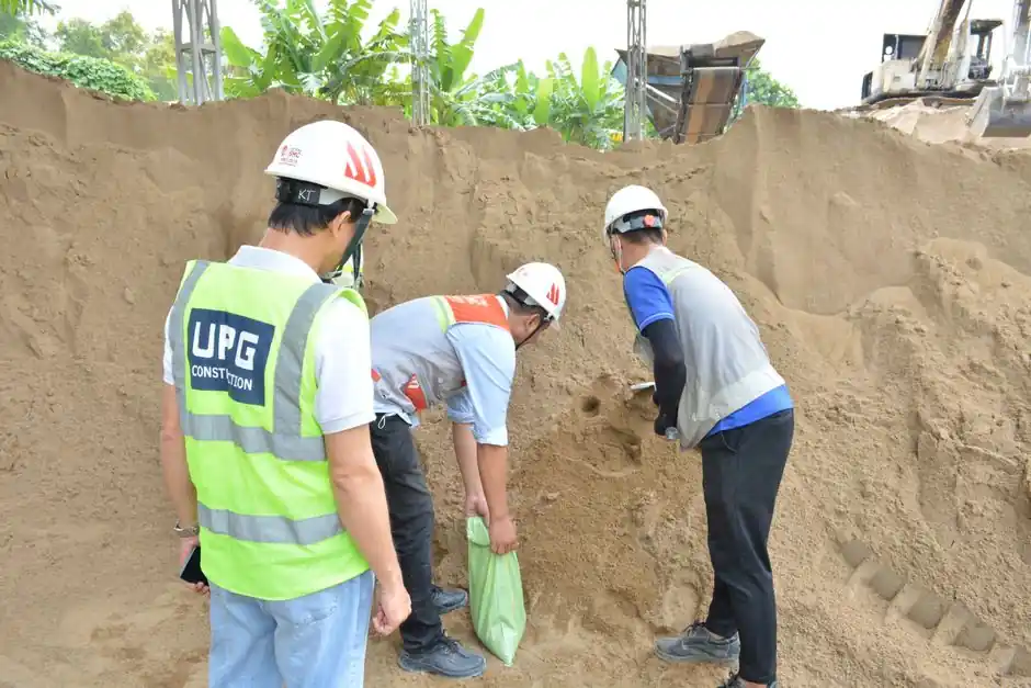
A 1:200 verticality tolerance permits a maximum panel deviation of 0.5% of depth, equal to 150 mm over a 30 m panel and 300 mm over a 60 m panel.
Hydromills are appropriate for deeper diaphragm walls and for walls located in granular materials and soft rock [S4].
Interpret 1:200 as a Depth-Dependent Offset
Verticality is normally expressed as a ratio because the same inclination produces a larger horizontal departure as excavation depth increases [S3][S4].
The calculation is straightforward: maximum deviation equals depth divided by 200. A 10 m excavation permits 50 mm, a 20 m excavation permits 100 mm, a 30 m excavation permits 150 mm, and a 60 m excavation permits 300 mm when the specified tolerance is 1:200 [S3][S4].
That interpretation matters because 1:200 does not mean a fixed 50 mm error at every depth. It permits 0.5% of the measured panel depth, with the actual acceptance criterion depending on the project specification and the length or exposed face against which deviation is assessed [S3].
Match the Equipment to the Depth Range
Standard grabs weigh 8–20 tonnes, while hydromills are used for deeper diaphragm walls and in granular materials and soft rock [S4].
A London excavation used hydraulic grabs for walls 1.2 m thick and 60 m deep, with the panels passing through made ground, London Clay, Harwich Beds, the Lambeth Group, and Thanet Sand [S3]. The case demonstrates why verticality criteria cannot be separated from ground conditions, panel geometry, and excavation depth.
Grabs weigh about 8–20 tonnes and are mounted on hydraulic base cranes of roughly 80–120 tonnes to provide stability and line pull [S4]. The diaphragm wall grab therefore operates as a suspended excavation tool whose verticality depends on the crane, guide system, operator control, trench conditions, and the measurement process.
This equipment is suitable for deep excavation support and groundwater cutoff where panel-by-panel construction can be controlled. It is less suitable where the required depth exceeds the verified reach of the grab, where obstacles prevent controlled excavation, or where ground conditions make panel-edge geometry unreliable.
Compare Grabs, Hydromills, and the 1:200 Criterion
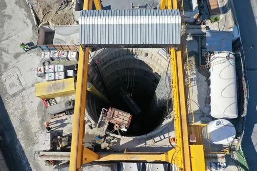
Against depth, soil condition, and geometry control, a hydraulic grab offers a practical solution for excavation to about 50 m, while a hydromill is the stronger option for deeper walls, granular materials, and soft rock [S4].
That capability does not make the 1:200 allowance irrelevant, because allowable offset still grows linearly with depth: 150 m at 1:200 corresponds to 750 mm.
Control the Full Panel Geometry
The measurement sequence has three distinct checks. Inclinometers establish the panel inclination, calipers verify thickness or trench width, and depth measurements confirm the excavated panel length. No single instrument provides complete acceptance of panel geometry.
Guide walls control alignment and elevation at the top of the excavation, while the grab or cutter must remain aligned as depth increases [S1]. The project specification cited for the 60 m Central London walls allowed maximum verticality of 1:200 over the exposed face, but the project team identified a risk that pilot holes and other deviations could undermine that requirement [S3][S8].
Operators need a defined baseline, a stated reference length, and a clear rule for whether the tolerance applies to the full excavated depth or a specified exposed face.
Recognize the Consequences of Excavation Error
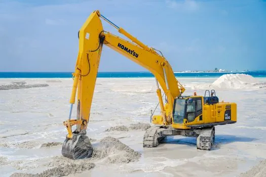
A 1:200 tolerance permits 100 mm of deviation at 20 m, 200 mm at 40 m, and 250 mm at 50 m, so panel-edge alignment errors can become significant at excavation scale [S3][S4].
Because a diaphragm wall is assembled from discrete panels, each excavation stage affects the final structural continuity and verticality of the wall [S6]. Diaphragm walls are constructed in discrete panel lengths typically ranging from 2.5 m to 7.0 m [S4].
Overexcavation or an inclined panel can reduce the effective overlap at adjacent joints, complicate stop-end installation, and create gaps that affect watertightness. Verticality errors can also consume excavation width, affect the placement of reinforcement cages, and complicate wall-head trimming and connection to bracing or slabs [S1].
The failure mode is therefore cumulative. A deviation accepted at the guide wall grows with depth, and minor deviations at several panels can produce a discontinuous wall alignment rather than a uniform lean.
Specify Testable Verticality Requirements
For a 60 m panel at 1:200, the calculated offset is 300 mm, but the specification must identify the control line and the length over which the ratio applies. A practical minimum information set includes panel width, panel length, excavation depth, allowed deviation, baseline, monitoring method, and the point at which work must stop for engineering review.
North American practice extends beyond 200 ft, while hydromill excavation can exceed 500 ft, or 150 m [S2]. At those scales, the same ratio still governs acceptance, but the numerical offset becomes large enough that deviation should be reviewed against panel geometry, structural alignment, and joint performance.
The next trackable checks are the approved panel measurement record, the as-built deviation at full depth, and the deviation distribution across adjacent panels. Reviewing those values against the stated 1:200 reference length is more defensible than judging a grab by its nominal depth rating.