D&S uses two independent systems to continuously monitor the exact position and orientation of the diaphragm wall grab, allowing corrections at the slightest deviation and detailed reporting on completed structures [S5].
The equipment decision is more than a camera purchase: cab architecture, working clearance, hydraulic-grab geometry, and independent verticality instrumentation must be matched to panel width and site headroom.
Visibility Must Cover More Than the Grab
Deep-panel monitoring requires the operator to see the guide wall, trench opening, slurry level, neighboring panels, and the grab itself, while cameras supply views blocked by the boom or trench wall [S2][S6].
A low-headroom configuration changes the problem because the cab must retain useful sightlines where the carrier itself occupies most of the available vertical space [S1]. The DHG-LT addresses this constraint with a 2,800 mm trench length, 800–1,500 mm trench width, 15–22 t operating weight, two 450 kN cylinder forces, four steering plates, and an optional TD4 turning device [S1].
That geometry makes a site survey decisive. Operators should mark the cab sightline, guide-wall reference points, slurry reference plane, and panel joint positions before production excavation. The objective is to see whether the trench follows the planned geometry without relying on the operator's memory of a view seen seconds earlier.
Position Sensors Do Not Replace Direct Observation
The GB50 can excavate diaphragm walls with thicknesses ranging from 600 mm to 1,500 mm and depths of up to 80 m [S5]. Machine position and orientation require separate measurement.
D&S uses two independent systems on its GB50 system: Bauer-integrated sensors and the Jean-Lutz system. These continuously monitor the grab's position and orientation, support correction when deviation appears, and provide a record of the completed structure [S5].
For deep work, direct observation remains necessary because instruments measure machine attitude and position rather than every visible interface between trench, guide wall, slurry, and adjacent panel. The practical monitoring loop is: observe the trench and slurry surface, compare the displayed position with the reference line, correct the grab, then verify that the corrected path appears in the instrument record.
Choose the Cab for Clearance and Control Visibility
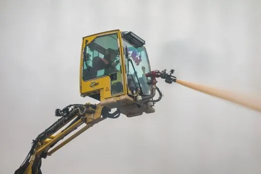
Diaphragm-wall machinery must provide visibility without exceeding the available headroom or interfering with grab steering, turning, and hose routing [S1][S6].
Three criteria separate the principal configurations. The DHG-LT is a low-headroom hydraulic grab developed for use with the GB 50 on projects with limited working heights [S1]. Second, working envelope favors the rope-guided DHG-V, which covers 2,400–3,800 mm trench lengths and 600–1,500 mm trench widths, with 1,200 kN or 1,800 kN cylinder force [S4].
The DHG-LT has four steering plates and can be equipped with the optional TD 4 turning device [S1]. Against these criteria, the DHG-LT is stronger where overhead clearance governs, the DHG-V offers greater trench-length and width adjustment, and a sensor-heavy configuration is necessary where verticality deviations must be corrected repeatedly.
Visibility Checks Must Follow the Excavation Sequence
Guide-wall alignment, slurry stability, and trench verticality must be checked at the stage where each defect can still be corrected [S2].
Before full-depth excavation, the slurry circulation system must be operational, and the starter trench must be filled with bentonite or polymer slurry so the pump remains submerged [S2]. The guide wall then serves as the horizontal alignment reference, supports the upper soil layers, and guides the grab vertically [S2].
During primary-panel excavation, operators must monitor trench verticality and stability continuously because panel dimensions, soil conditions, and equipment determine achievable panel length [S2]. Slurry density, viscosity, sand content, and pH also require continuous tracking before concreting [S2]. The cab should therefore expose the guide wall and trench opening, while the instrumentation panel presents position, orientation, and deviation data without blocking the physical sightline.
Recognize the Limits of Cab-Based Monitoring
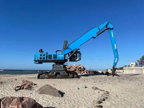
Visible obstruction is an equipment constraint rather than a camera defect: a grab hanging below the cab can conceal the trench interface even when the camera lens is clean [S1][S6].
Operator-cab design can improve comfort and visibility, but neither feature proves panel geometry on its own [S6]. The GB50 supports diaphragm walls with thicknesses of 600 mm to 1,500 mm and excavation depths of up to 80 m [S5].
Deep panels also create access and cleaning problems around lenses, screens, windows, and cameras. Fogging, slurry splash, and mechanical vibration can degrade the image at the exact point when the operator needs it. Specification teams should therefore define sight angles, camera coverage, illumination, washer and wiper provisions, screen placement, and control reach, then verify them under the selected carrier and grab geometry.
Specify an Integrated Monitoring Package
A defensible visibility specification combines cab architecture, position registration, steering controls, and documented inspection points rather than treating visibility as one accessory [S4][S5].
The minimum procurement record should state the carrier and grab combination, trench width range, operating depth, working radius, cylinder force, steering configuration, and selected sensor packages. For the DHG-LT, those records would include a 2,800 mm trench length, 800–1,500 mm width range, 15–22 t weight, two 450 kN cylinder forces, four steering plates, and optional TD4 turning device [S1].
Acceptance testing should include a dry-site sightline check, a controlled panel trial, slurry-surface observation, comparison of independent position systems, and verification that deviation corrections are visible in both the physical view and recorded output [S5]. For broader production planning, Diaphragm Wall Grab Capacity and Panel Production addresses how equipment capacity translates into panel output.
Track two procurement signals before approving a deep-panel package: confirm the installed cab's clear view of the guide wall and trench interface, then verify that position and orientation data remain readable during simultaneous steering, turning, and slurry operations.