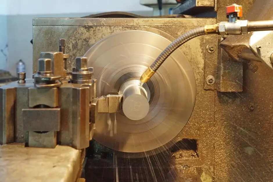
A balancing arbor should fit the rotor bore with controlled clearance, measured runout, and repeatable radial location, because bore and arbor errors directly contaminate the balancing result [S1][S2].
The arbor supports a bored disc or wheel during dynamic balancing, while the rotor weight, speed, correction method, balance tolerance, and production volume determine the machine and tooling package [S5].
Arbor fit, bore tolerance, and correction
That dimensional sensitivity explains why nominal arbor diameter alone is not a valid sizing basis.
The finished rotor bore and the balancing arbor form a temporary location system. A precision shaft inserted through the bore does not automatically remove errors caused by bore clearance or tooling error [S2]. If the arbor runs eccentrically, tilts, or shifts between setups, the measured unbalance includes the fixture rather than representing the rotor alone.
For rotors with shafts or journals, the balancing machine can support the rotor directly. For a disc with a bore, a vertical machine and an arbor are generally required [S5]. This distinction also makes the arbor a controlled support component rather than a convenience sleeve.
Select the arbor from the measured bore
The correct starting point is the rotor's measured bore diameter at the balancing location, not the drawing nominal diameter alone. Record the bore condition, including roundness, taper, and the position where the arbor will contact it. Small-part specialists describe micro balancing as requiring a precision interface to tooling and special concern for repeatability on and off tooling and balancing arbors [S1].
The arbor must be precision machined, stable at balancing speed, and repeatable when the rotor is removed and reinstalled. Dynamic balancing of small rotors requires a precision interface to tooling and special concern for repeatability on and off tooling and balancing arbors [S1]. The arbor's own eccentricity, cylindricity, and mounting error therefore need to be controlled rather than assumed away by the balance machine.
A practical sizing sequence is to establish the acceptable bore-to-arbor clearance, machine the arbor to suit the measured bore, measure its runout under the intended support arrangement, and then record the initial unbalance with that tooling. The rotor mass and geometry remain essential because one bore dimension cannot define an acceptable support condition by itself.
Compare the three practical mounting options

A bored rotor can be supported by a dedicated arbor, held on its production shaft, or balanced as an assembled unit in a fixture.
On repeatability, the dedicated arbor must be assessed against its bore, while the production shaft is judged against the rotor's own journals. The assembled-fixture option shifts the design problem from bore clearance to fixture repeatability and setup discipline [S1][S2].
Match the arbor to machine and balance requirements
A balancing machine should be selected from the rotor outward using seven facts: shape, minimum and maximum weight, maximum diameter, required tolerance, number of correction planes, drive method, and production volume [S5]. For a bored disc, the bore size is part of the tooling envelope, but the balancing machine still needs sufficient weight capacity, swing, spindle accuracy, and correction capability for the complete rotor.
Machine selection depends on the rotor's shape, size and weight range, tolerance, number of planes, drive method, correction method, and required production volume [S5].
Machine selection includes determining whether one or two measurement planes are needed [S5]. The arbor must remain valid for whichever correction planes the selected process requires.
Drive, correction, and runout constraints

Machine selection includes determining how the rotor will be driven [S5]. A disc with a bore, such as a flywheel, brake disc, or pulley, generally uses a vertical balancing machine [S5].
Correction must be planned before the arbor is accepted. Rigid rotors can be corrected by placing correction material at a defined radius to counteract the measured unbalance [S7]. The available correction radius, the arbor's retention method, and the required number of planes all affect whether the proposed tooling is practical.
Verify the setup before trusting the balance result
Verify arbor runout before mounting the rotor, then repeat the check with the rotor installed. Record the arbor identifier, rotor identity, bore measurement, support arrangement, rotation method, and balance result. That traceability matters because removal, cleaning, reassembly, or a change in arbor orientation can otherwise alter the setup. [S2]
ISO 1940-1:2003 provides requirements for rigid-rotor balance tolerances, while ISO 11342 covers methods for balancing flexible rotors. If rotor-specific limits are unavailable, balance criteria may be derived through the applicable vibration and machine considerations identified in the rotor-balancing guidance [S2][S4].
Dynamic balancing is not a substitute for poor machining, eccentric assembly, or distorted components. Material defects, casting porosity, eccentric machining, key and keyway stack-up, corrosion, wear, and uneven deposit buildup can all create or change unbalance [S2]. Correcting a rotor to mask a poor interface can produce a passing bench result followed by unacceptable installed vibration.
Specify the arbor as controlled production tooling
The most defensible arbor specification states the measured rotor bore, permitted radial clearance, arbor material and surface finish, maximum runout at the rotor location, support method, retention method, allowable speed, correction-plane arrangement, and required repeatability. Where the production volume is significant, record the fixture or arbor as an assembly instruction so operators mount the same controlled interface every time [S1][S5].
A one-off balancing job can often start with a measured bore and a trial arbor. Repeat production needs more: setup variation, tooling wear, inspection frequency, and the method for handling bore sizes that vary across a production batch. A balancing machine with the right capacity and tolerance still cannot recover repeatability from an uncontrolled arbor-to-bore interface [S1][S2].
For machine layout and tooling comparison, Horizontal vs Vertical Balancing Machines: Selection Matrix by Rotor Geometry provides the geometry-driven selection context. The next verification step is to inspect the first-off balance result across repeated removals and installations, with drift in residual unbalance treated as a tooling or setup problem rather than rotor variation.