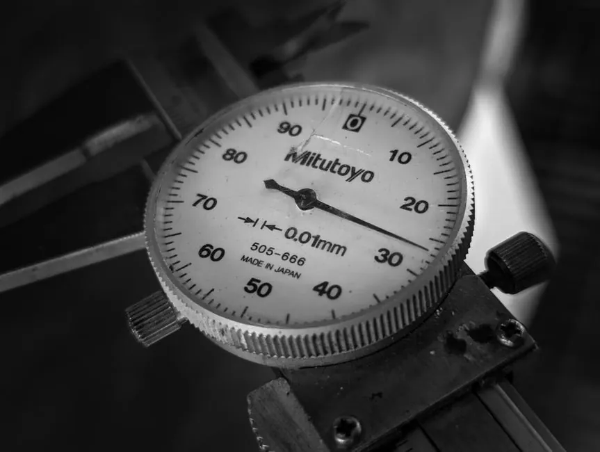
For as-built reverse engineering, the decisive spec is volumetric accuracy under 0.1 mm combined with point spacing tight enough to resolve 0.2 mm features, the threshold most CAD surfacing tools need before they can fit clean parametric geometry [S2].
Handheld structured-light systems now cover the bulk of brownfield documentation work, while long-range laser scanners and tracker-based rigs handle large piping, structural steel, and plant geometry. The market split in 2026 mirrors what vendors are actually quoting: 5–10 kg portable scanners with built-in cameras versus tripod-mounted laser arms for fixtures and assemblies [S2][S3].
Accuracy, Point Density, and Tracking: the Three Specs That Decide Fit
Volumetric accuracy in the 0.02–0.05 mm range is the practical ceiling for short-range structured-light scanners used on machined parts, and 0.05–0.1 mm is the realistic band for handheld units tracking over a 200–300 mm stand-off [S2]. A single-shot accuracy figure on a datasheet is not enough; what matters is the deviation across the full working volume after alignment, which is why vendors quote volumetric accuracy rather than just point accuracy.
Point density is the second decision driver: modern metrology-grade scanners deliver 0.1–0.2 mm pitch at 100 mm working distance, dense enough that a 0.5 mm fillet reads as a curve rather than a faceted polyline [S2]. The third pillar, tracking stability, is what separates a scanner that works in a lab from one that survives a shop floor; infrared or laser tracker fusion, marker-based reference frames, or simultaneous localization and mapping (SLAM) are the three approaches published in 2026 product literature [S3]. When tracking drops, registration error compounds, and the final mesh drifts 0.3–0.5 mm even if the raw sensor accuracy is 0.03 mm.
Scanner Types Compared: Handheld Structured-Light, Laser, and Tracker-Based
Handheld structured-light scanners in 2026 cover the 0.05–0.1 mm volumetric accuracy band, weigh 0.8–1.5 kg, and operate at 1,000,000–3,000,000 points/s; they are the default for small-to-medium parts under 1 m [S2]. Their weakness is on shiny, dark, or transparent surfaces, which is why vendor accessory lists now routinely include 6 mm, 12 mm, and 3 mm reference markers plus AESUB Blue vanishing spray for low-contrast parts [S3].
Long-range laser triangulation and time-of-flight scanners take over above 1 m part envelopes, where working distance kills structured-light field of view. They give 0.1–0.3 mm accuracy at stand-offs of 300–500 mm and drop to millimeter-level at 10 m+ ranges used in plant scanning. Tracker-based rigs, where a laser tracker follows a probe or scanner, push volumetric accuracy below 0.05 mm on large assemblies because the tracker anchors the coordinate frame instead of relying on feature matching. The trade is speed: a tracker-based scan of a 2 m turbine housing is a 4–6 hour job versus 20–40 minutes for a handheld pass over the same part [S2].
Who It Is For, and Where It Fails
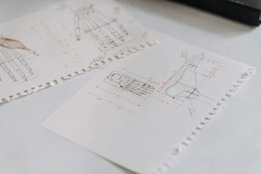
3D documentation scanning fits reverse engineering of legacy parts without OEM drawings, dimensional validation against as-built conditions, modification of existing assemblies, and CAD reconstruction of components that suppliers no longer support [S1]. It is the right answer when the original design data is missing, outdated, or known to drift from the physical asset.
It is the wrong tool for sub-50 µm tolerance work that needs CMM-grade traceability, for parts with deep internal cavities the optical line of sight cannot reach, and for in-motion measurement on a production line where the scanner cannot be stabilized. Sub-50 µm work still belongs on a coordinate measuring machine; optical scanners are metrology tools, not replacements for tactile probing on tight-tolerance datum schemes.
From Point Cloud to Fabrication-Ready CAD: the Workflow Constraint
The scan is the foundation, not the deliverable; a clean mesh-to-CAD path is what makes a scanner actually useful for fabrication [S2]. Scan data arrives as a point cloud, which is then meshed into an STL polygon surface, and only then imported into reverse-engineering software where parametric surfaces (cylinders, planes, splines) are fit over the mesh to produce STEP, IGES, or native CAD files that machine shops can actually cut from [S1][S2].
For dense point clouds exceeding 100 million points, decimation to 5–10 million before meshing is the practical sweet spot, and the modeler should expect 2–8 hours of CAD reconstruction time per part after a 20–40 minute scan session [S2]. The output format list that buyers should require includes STEP AP242, IGES, STL, and the native CAD format the customer's machine shop runs, because STL alone is not editable in parametric CAD [S1].
Selection Criteria in Practice: a 4-Point Comparison

Across the main scanner categories, four criteria separate the options: (1) volumetric accuracy, where tracker-based rigs hit 0.02–0.05 mm, short-range structured-light hits 0.05–0.1 mm, and long-range laser sits at 0.1–0.3 mm; (2) working volume, where handheld units cover 0.05–1 m parts, long-range scanners cover 1–50 m scenes, and tracker rigs cover 0.5–5 m assemblies; (3) surface tolerance, where shiny or dark parts need spray or marker reference frames regardless of category; (4) throughput, where handheld scanning clocks 20–40 minutes per medium part, long-range scanners drop to 5–15 minutes per setup on plant geometry, and tracker rigs run 4–6 hours per assembly [S2][S3].
Buyers should weight these criteria against the actual part mix, not the showcase demo: a shop doing one-off legacy parts benefits most from tracker accuracy, while a plant documenting 10 km of piping benefits most from long-range laser speed even at the cost of millimeter-level accuracy.
Standards, Validation, and Documented Tolerances
Specification sheets should quote volumetric accuracy following the vendor's own test protocol, but the project-level validation step is to re-scan the fabricated part and overlay it against the design model before installation, the explicit check vendors recommend and that closes the loop on dimensional fit [S1]. For work tied to ASME Y14.5 or ISO 1101 tolerancing, the scanner output feeds the CAD model, and the GD&T callouts stay in the drawing layer, not the mesh layer.
Two trackable signals through the rest of 2026: vendors are pushing markerless SLAM tracking into mid-tier handheld units to remove the reference-marker workflow on large parts [S3], and more suppliers are bundling the EXModel-class or equivalent reverse-engineering software with the hardware, collapsing the two-step hardware-plus-software procurement that slowed adoption in earlier years [S3]. For related metrology context outside the optical domain, see this AGMA service factor note on composite gearbox selection and this phased-array pulser/receiver count comparison; for background on the structured light scanner working principle and the broader 3D scanner landscape, refer to the encyclopedia entries.
Component reference pages worth checking: engineering plastic.