
A1 and K1 links connect slats, fixtures, scrapers, and other parts to roller chain, with A1 providing a one-hole attachment on one side and K1 providing one hole on each side [S1].
The attachment code must be matched to the chain family, mounting shape, repeat spacing, and installed direction, then checked against dimensions, operating load, and sprocket clearance rather than treated as a universal replacement specification.
A1 and K1 mount different fixture geometries
A1 is a bent-lug attachment with one hole on one side, while K1 is a bent-lug attachment with one hole on each side of the chain [S1][S6]. A1 therefore suits a fixture that needs a single attachment tab, whereas K1 provides two opposed mounting points for a fixture that must straddle or align to the chain [S1].
These definitions are not universal across manufacturers. Diamond calls its equivalent forms B-1 and B-2, while Tsubaki uses A-1 and K-1, and the interchange table shows additional variations among Renold, Drives, and HKK [S4]. The attachment code identifies a mounting pattern, not a complete conveyor or a guarantee of dimensional interchangeability.
For a fixture replacement, the useful records are the existing chain number, pitch, inside width, attachment side or sides, hole diameter, hole centerline, tab height, tab width, and installed direction [S1][S5]. A photograph can identify the general shape, but a dimensioned drawing is required to establish hole sizes, plate thickness, and mounting clearance [S1].
Use chain-size tables to control fixture fit
Published A1 and K1 tables provide separate dimensions for the two attachment styles.
Those dimensions scale materially with chain size.
The associated base-chain dimensions must also fit. These values define the mechanical envelope into which the fixture holes, bolts, and surrounding structure must fit.
Compare A1 and K1 against mounting criteria
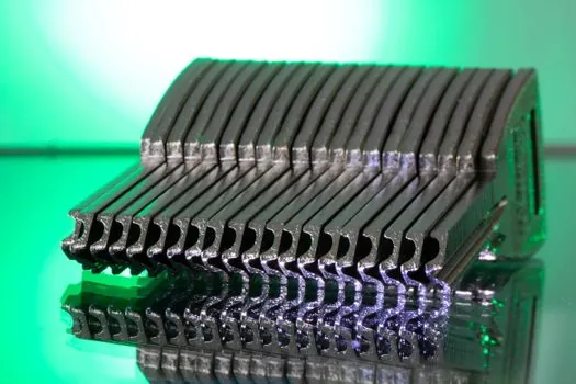
For one-sided mounting, A1 uses fewer attachment points and leaves the opposite chain side unobstructed. For two-sided mounting, K1 provides opposed holes but requires sufficient width for both tabs and for the fixture or fastener heads between or outside them [S1][S5].
A1 generally simplifies a single-tab fixture, while K1 improves alignment when a fixture uses two chain lines or needs matched hole centers. Neither style automatically carries more load because the chain size, attachment dimensions, tab width, pin link placement, and fixture geometry determine capacity [S1][S5].
Interchange requires matching more than the label. The cross-reference maps A-1 to Diamond B-1 and K-1 to Diamond B-2, but the referenced table explicitly serves as an interchange reference rather than a dimensional guarantee [S4]. The buyer should still compare hole diameter, centerline distance, tab dimensions, chain pitch, and attachment spacing against the supplier drawing.
Set attachment spacing as part of the purchase order
Attachment spacing must be specified whenever the type is ordered [S2]. Renold Jeffrey defines typical options as every pitch or every second pitch, with evenly spaced attachments placed on pin links unless another arrangement is specified [S5].
A full-pitch arrangement gives more attachment opportunities along the chain, while an every-second-pitch arrangement reduces the number of mounting points and changes the fixture load distribution. Neither arrangement should be selected without checking the slat pitch, chain length in pitches, sprocket positions, and the location of chain transitions.
Chain length is ordered by the number of pitches, including the connecting link, and is normally an even number for an endless installation [S2]. If an odd pitch count is unavoidable, the purchasing specification should identify whether a single-pitch or two-pitch offset link is required [S2]. These details determine whether the A1 or K1 pattern lands where the fixture needs it.
Connecting and base-chain construction affects serviceability

Spring-clip connecting links with slip-fit cover plates are standard through ANSI 60, while press-fit cover plates are offered for heavy-duty applications [S2]. Cottered connecting links are available in either press-fit or slip-fit construction.
Base-chain material and finish also belong on the order. Renold Jeffrey attachment chains are available in carbon steel, Hydro-Service coating, stainless steel, nickel-plated, Syno, and other options. Material selection should follow the attached fixture exposure, cleaning regime, corrosion risk, and operating temperature rather than the attachment code alone.
Integrated attachments fit specialized slats and jigs
Integrated attachment chain incorporates holes in special attachments for mounting slats, shoulder bars, angular bars, round bars, and shaped jigs [S3]. This construction suits a fixture designed around the chain assembly, but it is a different purchasing route from ordering A1 or K1 links as replacement attachments on standard roller chain.
The integrated route can simplify a made-to-fit slat or jig because the attachment geometry is part of the chain specification [S3]. A1 and K1 remain practical when the conveyor already uses the corresponding chain family and the fixture can be mounted to standardized tabs with confirmed dimensions [S1].
For either arrangement, the interface should be checked as an assembly. A properly categorized roller chain must engage compatible sprockets, while the selected conveyor chain must match the load path and operating method. Attachment selection is only one part of that mechanical system.
Build the RFQ around verifiable fit and loading data

An effective RFQ should identify the chain number, attachment type, attachment spacing, strand length in pitches, and number of strands [S5]. It should also include the mounted part’s function, product dimensions, weight, loading surface, material entry and exit arrangement, and whether one chain or parallel chains support the fixture [S1].
For replacement work, retain the chain identification and attachment measurements together, mark unverified dimensions, and include a complete fixture drawing [S1]. State whether the attachment is A1 or K1, whether it is one-sided or two-sided, and the installed direction rather than relying on an unexplained photograph [S1][S6].
For procurement traceability, include the base chain size, material or finish, attachment spacing, connecting-link construction, pitch count, strand count, and required lead time. Attachment-chain orders cover ANSI 25 through ANSI 160 [S2], while actual availability and dimensional equivalence must be confirmed against the selected supplier’s drawing and interchange data [S1][S4].
The first trackable procurement signal is a dimensioned RFQ that resolves A1 versus K1 geometry, chain size, hole dimensions, and pitch spacing; the second is a supplier drawing confirming the mounted fixture envelope before production.